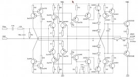
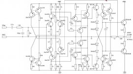
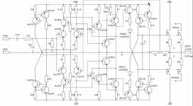
I want to hear opinions of this design. I've spiced it and gives me outstanding THD's at full power (note that the components are what I've found available here in Chile). I am new in this hobby, and I want to do a PCB with this circuit.
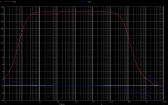
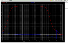
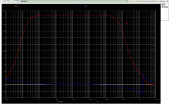
THD Frec Output amplitude Volts (8 OHM load)
0.028 400K 28.18
0.008 200K 30.20
0.0045 100K 30.78
0.0024 50K 30.93
0.0006 10K 30.98
0.0004 1K 30.98
Any comments?
Thanks in advance
Arturo
THD Frec Output amplitude Volts (8 OHM load)
0.028 400K 28.18
0.008 200K 30.20
0.0045 100K 30.78
0.0024 50K 30.93
0.0006 10K 30.98
0.0004 1K 30.98
Any comments?
Thanks in advance
Arturo
Attachments

looks good
That's some really good results...I'm a bit concerned that your models for the output darlingtons my be a bit iffy wrt frequency response/stability. Have you sanity checked them?
That's some really good results...I'm a bit concerned that your models for the output darlingtons my be a bit iffy wrt frequency response/stability. Have you sanity checked them?
correction to the schematic
I've heard concerns about the output darlingtons, are a little bit slow adding phase delay, but in this case are hard drived from previous stages. the cascode pass thru a follower before the voltage gain stage, [the challenge was maintain stability], the phase shift added by the darlingtons is negible far above the audible region.
I've heard concerns about the output darlingtons, are a little bit slow adding phase delay, but in this case are hard drived from previous stages. the cascode pass thru a follower before the voltage gain stage, [the challenge was maintain stability], the phase shift added by the darlingtons is negible far above the audible region.
Attachments

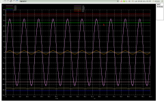
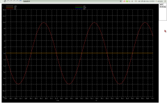
Checked BDX33, the simulation with the Motorola model gives same results, attached sine wave at 100KHZ, still flat band
ngspice 3 -> fourier 100000 v(4)
Fourier analysis for v(4):
No. Harmonics: 10, THD: 0.00297656 %, Gridsize: 200, Interpolation Degree: 1
Harmonic Frequency Magnitude Phase Norm. Mag Norm. Phase
-------- --------- --------- ----- --------- -----------
0 0 0.00263235 0 0 0
1 100000 30.7938 -6.8426 1 0
2 200000 0.000257071 -93.347 8.34814e-06 -86.504
3 300000 0.000764524 113.537 2.48272e-05 120.379
4 400000 0.000238637 49.485 7.74952e-06 56.3276
5 500000 0.000299639 -54.144 9.73052e-06 -47.302
6 600000 0.000121386 -139.2 3.94191e-06 -132.36
7 700000 0.000140829 123.56 4.57331e-06 130.403
8 800000 5.71412e-05 31.1615 1.85561e-06 38.0041
9 900000 7.07213e-05 -64.973 2.29661e-06 -58.13
Attachments
My concern would not be the phase delay of the Darlingtons so much as the thermal compensation to keep bias stable. Keep in mind that the driver is on the same die as the output device and is also heated. So you have one temperature coefficient multiplied by the next. Complementary Darlington class AB output stages require thermal compensation....
Good point CBS240, in fact the bias point changes, I've simulated with global temp's from 27° to 125° and the bias piont changes from -0.063 to 0.060 Volts and the bias current (class A) from 2.4A to 3.1A. I will do more acurate simulations keeping the signal circuit at one temp (35° to 65°) and the power circuit at a high temp (125° to 150°)
I did some thermal simulations. I found that darlingtons are not the issue, the signal circuit is dominant over the bias point, it changes about 500mv over a range of 60°. The darlinton temp was set to 100° constant at 3.2A bias current (class A). Maybe it be worth to add a DC servo (chip opamp OPA27)
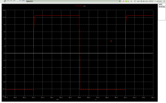
I changed de buffer with BD139/140 to increase the bias current of the buffer, which enhances the perfomance at high frec. ie:
THD @ 400KHZ full power lowers to 0.017, @ 100KC lowers to 0.034, @ 10KHZ 0.00078. Square wave is very clean with a slew rate of 17V/us.
I did some test using HEXFET's irf530/irf9450 (no lateral mosfets in Chile) but these devices are pure crap for quality audio at high frec., so I decided to keep the darlingtons. The dumping factor is 3800. I will desingn the servo and the PCB. I am an old BJT man and I feel BJT's perform a warmer sound than TUBES (mi old hamman kardon with KT-88 pentodes)
Attachments
Every transistor requires current to turn on. Once it is on, there is a finite amount of charge in the base of the transistor and when the input current is removed, there is a finite amount of time it takes for this charge to deplete. Or, you can apply a negative current to actively remove this charge to reduce the finite time it takes for the transistor to turn off by itself. At high frequencies this is required in order to better control the transistor, reduce distortion and prevent crossconduction.
If you physically connect the outputs to the BD139/140 devices (the ones with the collector connected to the rails) the heat from the outputs would cause their Vbe to decrease, thus providing a thermal feedback loop to the outputs. The problem is this may not be enough because the temp. coefficient of the Darlingtons is the product of the Tc from both devices inside the Darlington package. I once built a test circuit using Darlington OPT but I used a Darlington device for the thermal compensation. It still required fine tuning of the Vbe multiplier to accurately track the bias.
As for HEXFETs, if used as if they are conventional BJTs, they work as pure crap. BUT, Hexfets are not BJTs and work in a completely different manner. There are a few non-linear components, one being CISS and CRSS that corrupt the operation. These non-linear components are less pronounced in lateral fets but are still there. It is quite possible to build a very low distortion amplifier using hexfets or even planer stripe type diffusion mosfets that will work at 400KHz, but it requires a different approach and is not so simple to do correctly. They are designed as switching devices so there are inherent issues to deal with if one chooses to use them in a linear application. Many folks say they can't be used in low distortion linear amplifiers, but they are wrong. It just takes a bit more complexity, that which they are unwilling to do. For those folks, I suggest sticking to those nice linear expensive BJT's.
Incidently, if your understanding is up to it, here is an interesting paper regarding Darlington output transistors and how to improve thier operation.😉
Hi Artu,
interesting design but if I can be picky and if your software will allow, would you show your plots with a white background, please?
My tired old eyes find difficulty seeing the plot traces against the black background and if your amp is as good as it seems, I'd like to get as much information as possible.
Thank you,
Sandy
Artu,
Did you also check the DC stability / output DC offset? This is an improtant issue in a practical amp, which is not shown in any THD or other small-signal simulation. A DC transfer sim would show that. Maybe you need to add a servo to keep the output at 0V DC.
jan didden
Did you also check the DC stability / output DC offset? This is an improtant issue in a practical amp, which is not shown in any THD or other small-signal simulation. A DC transfer sim would show that. Maybe you need to add a servo to keep the output at 0V DC.
jan didden
Thank's CBS240 for your wise reflections, yes temperature is the real world devil, reality check ... I will investigate how to deal with this issue, I will study the paper you linked and try to found a simple and effective solution to the bias piont.
Best Regards
Best Regards
Yes Jan, I am aware that DC stability / output offset is critical I dont want to burn my speakers ha ha ... so as I qouted to CBS240. maybe the solution is to add a servo, but in the correct place (the current source of one of the input legs), and a quick main disrruptor in case of a catastrofic failure.
Best Regards
Best Regards
open loop numbers
here are the open loop small signal numbers:
input 100uVolts sine wave.
case 1 no load:
ngspice 3 -> fourier 200 v(4)
Fourier analysis for v(4):
No. Harmonics: 10, THD: 0.237629 %, Gridsize: 200, Interpolation Degree: 1
Harmonic Frequency Magnitude Phase Norm. Mag Norm. Phase
-------- --------- --------- ----- --------- -----------
0 0 -0.011294 0 0 0
1 200 9.8447 2.48044 1 0
2 400 0.0180756 -89.941 0.00183608 -92.421
3 600 0.0148404 0.0444251 0.00150745 -2.436
4 800 0.000552403 90.7164 5.61117e-05 88.236
5 1000 1.27651e-05 -128.43 1.29665e-06 -130.91
6 1200 6.73286e-07 50.899 6.83907e-08 48.4186
7 1400 4.48513e-07 179.723 4.55588e-08 177.243
8 1600 2.99622e-07 -169.68 3.04349e-08 -172.16
9 1800 2.64386e-07 -171.52 2.68556e-08 -174
case 2 full load (8 ohm)
ngspice 2 -> fourier 200 v(4)
Fourier analysis for v(4):
No. Harmonics: 10, THD: 0.295172 %, Gridsize: 200, Interpolation Degree: 1
Harmonic Frequency Magnitude Phase Norm. Mag Norm. Phase
-------- --------- --------- ----- --------- -----------
0 0 -0.0046857 0 0 0
1 200 9.57874 2.49983 1 0
2 400 0.0238388 -90.803 0.00248872 -93.303
3 600 0.015193 0.348435 0.00158612 -2.1514
4 800 0.000535662 91.9826 5.59219e-05 89.4828
5 1000 1.16477e-05 -99.136 1.216e-06 -101.64
6 1200 1.31745e-06 68.7126 1.37538e-07 66.2127
7 1400 4.78281e-07 -178.37 4.99316e-08 -180.87
8 1600 2.86609e-07 -169.86 2.99214e-08 -172.36
9 1800 2.57254e-07 -171.23 2.68567e-08 -173.73
the voltage open loop gain is about 95000, it's remarkable such low distortion in an open loop with such gain !!!
sorry for the black background
Attachments
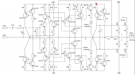
mosfet powered version
OK, I did a mosfet powered version to replace the output darlingtons. The mosfet are drived with the buffer set at low impedance in order to deal with the charge stored in the gates (wich is sustatial at high frecuencies 1nf cap). The numbers are slightly less (THD) than the darlington version, but I managed to deal with those HEXFETS IRF530 IFR9540 to obtain a decent distortion at high frecuencies (I want to hear all I can from a trumpet ie.). I will not put a servo becuase I obtained +/- 10 mVolts in the range of 30° to 100° (silicon temp), and I believe that 70° span is enough, only the fast protection needed to disrupt energy if something goes wrong. Note that I did not put a resistance in series with the gates, mainly because this topology is to be used by switching applications ??? (high dv/dt pulses to prevent mosfet instability), I guess not in a class A audio amp (there was a question about this, about a circuit without that resistor ???). The simulation showed that the inclusion of a resistor in series with the gate introduces spikes in the feedback loop, worsening a lot the response above 200KHZ, (in this topology), besides that, the gates HAS a resistance in series (the output resistance of the buffer), I dont know if it enough, I've heard values from 10 to 220 ohms ... comments please ...
THD's obtained at 65°
Frecuency THD Amplitude (Volts)
----------------------------------------
10KHZ 0.00076 30.9884
100KHZ 0.00859 30.8988
200KHZ 0.02810 30.6306
400KHZ 0.08599 29.6109
I want to hear all ... the bad and the good
Cheers to all
Arturo
Attachments

Hi
Simulations are a great tool, but there are a few issues to resolve in the circuit regarding the output mosfets if you intend to build an actual real amp. First a gate stopper resistor is needed to dampen the RF oscillator that the mosfet will inherently become in the circuit. Even better, a gate Zobel filter. Low Z driver stage is good but will not help with the inherent instabilities of the mosfets.
You will need to place a Zener diode, like 15V, between the gate and source of each mosfet because the metal oxide layer has a breakdown voltage of only +/-20V, they need protected. These mosfets are Vertical types and will require thermal compensation like as with BJTs. However, due to thier reduced transconductance at lower bias currents, they will be much more forgiving. Note also that a proper bias for these devices will be somewhere between 100mA - 300mA; this is related to the reduced transconductance at lower currents. There is some more detailed information in this paper about the inner workings and use of power mosfets for linear applications.
[snip]THD's obtained at 65°
Frecuency THD Amplitude (Volts)
----------------------------------------
10KHZ 0.00076 30.9884
100KHZ 0.00859 30.8988
200KHZ 0.02810 30.6306
400KHZ 0.08599 29.6109
[snip]Arturo
Arturo,
With numbers like this it is highly unlikely that these are realistic. Based on many experiences of turning a simmed design into hardware I would say they are MUCH too good to be true. I think others have commented on the reliability of spice device models in particular MOSFETs.
Furthermore, a spice THD sim is always a small-signal sim, and the actual input- and output levels (like your 100uV input or 30V output) are disregarded. If you want to look at actual signal levels and distortion you should do a fourier sim which is a large signal (also called transient) sim.
Let's see the fourier results.
jan didden
- Status
- Not open for further replies.
- Home
- Amplifiers
- Solid State
- opinions