Thanks to tiefbassuebertr; you lead me to the upside down NPN driver transistor D40D13.
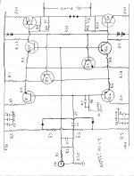
And now some thing to whet your appetites:Attached is a drawing I hesistate to call a schematic in fear of violating Belles IP (Intellectual property) that's about 25 years old!
some disclaimers & assumptions:
1. Q1-Q6 as the NPNs in this collection were marked on their faces "EBC."
2. EBC looking left-to-right @ the faces of Q7 & Q8.
3. I assumed the 2 diodes* connected to Q5 & Q6 were Zeners* because they looked like the 4 on either side of R23. Yes its possible I have the bias reversed, drawn based on what I interpreted as their* cathodes.
4. R12 has something in parallel w/it - markings suggest a cap. Will check the other channel for same
5. forgot to label resistors between the drivers and PS rails-let's call them R23 & R24; 100 ohms BTW
6. R15-18 same value. O O Bk gold 33 ohms I believe.
Finally I think R23 could be the "Bias" resistor.
I leave this to those w/ far more brains & experience than me.
Next post I will provide more detail w/a parts list. a couple of the resistors do not use standard color coding requiring removal to test.
Thank you all very, very much
tony
Thank you for the schematic of front-end. Topology looks like CAIRN-EZO Studio1 and 4808 power amp (see attachement - all notes in German, not in English !!!) But in your schermatic from David Belles additional current sources for the differential amps was introduce, while by Cairn only resistors in use on this place.
Attachments
Last edited:
From my Blackberry on a coffee break: Tonight I will remove the other* channel* from the chassis to help w/parts list. After I posted my "drawing," took a quick glance at it* to discover its "R14" were 2 color-coded resistors.
Also I make no claims that my drawing is 100% correct-like those 2 zeners... I expect to improve accuracy w/the parts list.
* to avoid violating Belles' IP dogma
Many thank again
Merry Christmas tony
Also I make no claims that my drawing is 100% correct-like those 2 zeners... I expect to improve accuracy w/the parts list.
You're Welcome!Thank you for the schematic of front-end. Topology looks like CAIRN-EZO Studio1 and 4808 power amp (see attachement - all notes in German, not in English !!!)
Dave was ZERO help. I refer to it as MY drawing* created w/my dogmatic persistance & scant electronic knowledge. Much of aquired from the wonderful people like you on this and other forums kind enough to help.But in your schermatic from David Belles ...
* to avoid violating Belles' IP dogma
Please tell me what parts (from my drawing) make up the current source. Can't view your attachment right now. I might not recognize the differences even if I could....additional current sources for the differential amps was introduced...
Many thank again
Merry Christmas tony
Please tell me what parts (from my drawing) make up the current source. Can't view your attachment right now. I might not recognize the differences even if I could. Many thank again Merry Christmas tony
For the differential amp Q1/Q5 the according current source is Q3/R11 and for the differential amp in the negative rail the according current source is Q4/R12. R23 determine the reference current through the zener diodes. and the idle current through each differential amp are the Zener voltage reduced by Ube voltage (approximately 600mV until 700mV) divided by resistor value of R11 resp. R12.
BTW - you must exchange the collector and emitter symbol of all transistors in your drawing.
Commonly I haven't see zener diodes at this place (in your drawing without device number), instead that either LED's or two normal diodes in serial (like 1N4148) mostly in use. Then the voltage is between 1200-1400 mV (normale diode) and 2000-2300 mV (LED green, blue or yellow).
Last edited:
Tiefbassuebertr: thank you for the .pdf. It helped me to better understand my amp & this crazy hobbie a little more.
Last night I discovered several mistakes on My Drawing. 2 major & 2 minor.
1: Omission of naming the 3.3 ohm resistor grounded near input.
2: 2 "R23s". Re-name the resistor between the Q3/4 bases & 4 Zeners, R25.
3: Q3 & Q4 ARE connected to the CORRECT PS rails.
Connect Q3's collector to R16/18.
Connect Q4's collector to R15/17.
Next edition will reflect these changes plus corrected emitter & colector connections. (thanks here, too!).
Merry Christmas tony
Last weekend, got busy w/2 DMMs & soldering iron to test resistors w/non-standard markings/color coding. Also tested some w/color-coding to verify I read them correctly.
Comparison-tested* transistors* from both channels hoping to uncover SOMETHING.
* did not remove from board
The only thing I noticed is a tiny solder splash between Q2's collector & the artwork connecting R4, R6 & a diode. Also no LEDs on PCBs.
I hope to have time to reassemble. Then test for DC offset on the hope the splash was the problem. If not, then take point-to-point voltage readings between channels in the hope to uncover the problem component.
Failing all take the steps that an earlier reply suggested to test components, along the way seek out suitable replacement parts.
Parts list and updated Drawing almost ready.
Merry Christmas and thanks to all, tony
Last edited:
readings
Subject line says it.
For sure I'll need to source some replacements. Posibly as many as 24 in all.
hope you had a happy one & can import the data. You may notice different offset readings; can't explain except posibly the "splash" I mentioned in a previous post
I'm sure many of you w/ just a glance would see the problem(s) children.
thanks for your help tony
Attachments
Last edited:
Hi Tony,
I thought I would mention that the zener diodes you show in your schematic are not that uncommon. All, the voltage drop across a red LED is closer to 1.85 VDC. The red LED works really well because it compensates the transistor very closely for changing temperature. That's why I create current sources that way.
The higher zener voltage means that the output impedance of the current sources in the Belles are higher than the same current generated with an LED, pair of silicon diodes, varistor (anyone remember those?) or "ring of two" type current source. That's because the resistance from emitter to rail in your current source is much higher.
I haven't studied all the additional information yet, that will be a while. Note though, you are using a complimentary differential pair. That means that it's important that all four transistors have the same beta. (= matched for current gain)
Don't go replacing parts without a good reason. I just repaired an amp that had an oscillation issue in addition to it's other easily found problems. Brainiac used transistors that were not suited to the application. That means you can easily create new problems for yourself.
-Chris
take your time. I value insight from any one who knows more than me. BTW I'm not certain any diodes are zeners. No LEDs.anatech said:...I haven't studied all the additional information yet, that will be a while.
I refer you to "my drawing"-I assume those "4" are Q1/2/5/6.anatech said:...using a complimentary differential pair. That means that it's important that all four transistors have the same beta. (= matched for current gain)
-Chris
I don't need any more problems w/these amps. Study Post #23 or 24 for "drawing" corrections & the readings (attachment) I took over the weekend.
Yeah I have some trAnsistors to bench test. I think the readings hint Q3/4 have problems.
Thanks for your help. I welcome future input. Tony
Last edited:
updated drawing, parts list, and voltage readings
You will see zener diodes on the drawing in the next post*. I'm not certain they are.
* havta re-scan; current won't upload.
My gut tell me that when I'm equipted to test transisitors, Q3/4 should be first up at bat.
An earlier post suggested R25 controls bias.
Finally I'm looking for replacement parts.
thanks in advance tony
Attachments
Last edited:
- Status
- This old topic is closed. If you want to reopen this topic, contact a moderator using the "Report Post" button.
- Home
- Amplifiers
- Solid State
- will pay for Belles 1 Series amp info & Schematic