I used some paint´s thinner, R110 it´s the name. It is like light oil, but very strong and smell hard, but nice in the few seconds, I recommend to use dust mask with smelling filters. INSIDE? an array made by transistors, low noise I guess, maybe two fets, need to be sure, since no label or letters over devices, erased by AR people, looks like an op amp array, very similar to the mark levinson modules, I will work on schematic and the share with all you guys. One of my freinds told me he found an old round octal op amp in one o those modules , but I am not sure if it is a real AR module.
Anyway, I will try to replace the circuit by the LM4562 very very nice quality OP AMP used in many hi end brands as a secret weapon, limited only by supply voltage for this case.
Anyway, I will try to replace the circuit by the LM4562 very very nice quality OP AMP used in many hi end brands as a secret weapon, limited only by supply voltage for this case.
I really wish you would repair the original circuit.
When I was younger I also felt the desire to improve almost everything. But with time I found out, that when it comes to "classic" and famous stuff, I have found much higher pleasure by rapairing the stuff true to the original circuit.
Yes a technical 'improvement' is definitely possible, both for old stuff like this an also newer stuff, but you loose the charm, the originality, the uniqeness of the gear.
Think of it like having a vintage Mercedes with a broken engine, and then repairing it with an new Opel engine. The new engine might be technically superior...but not as charming and original as the old one.
Just my view - disregard it if you disagree mtubes - but we are still curious to see the geniousness of the original gain module.
")
When I was younger I also felt the desire to improve almost everything. But with time I found out, that when it comes to "classic" and famous stuff, I have found much higher pleasure by rapairing the stuff true to the original circuit.
Yes a technical 'improvement' is definitely possible, both for old stuff like this an also newer stuff, but you loose the charm, the originality, the uniqeness of the gear.
Think of it like having a vintage Mercedes with a broken engine, and then repairing it with an new Opel engine. The new engine might be technically superior...but not as charming and original as the old one.
Just my view - disregard it if you disagree mtubes - but we are still curious to see the geniousness of the original gain module.
completely agree with you Nrik, but sometimes old parts are not in the market for many reasons. Specially when you are living in a foreing country as MEXICO. I will try to find out some similar transistors and fets to fix it, if not I will replace with new stuff, because it could be the only chance to roll the amp up. For example I have an old Indian bike , a 1931 Chief , it needs some engine rings and a good cylinder hard to find both for reasonable price. My only chance to see the bike runs again is to improve a new EVO engine, it is the most close option to the original one. Also have a lotus 1974, gasket head and piston broken, to fix it ???? hard not many lotus of that year only 274... to get a new engine of that type its hard and expensive if you do not have a JUNK deposit close to you . As an Engineer ,I like the lotus design honestly, pretty much. But if I not find the spare parts or a working machine, probably shall to improve a ford 302 engine instead its 4 cylinder sweet purrs powerfull engine. Thax for your point of view , clompletey agree . CHEERS!
Hi again.
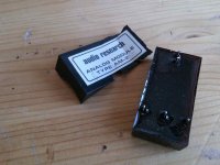
Bought a defective D100A with multiple defects, among them a missing module 2.
Tried paint thinner (toulene) on the remaining module 2 - no luck.
Mtubes it would be really appreciated if you would post some images or reverse engineer the schematic of the module.
Anyway: reading the schematic check out the 6.2v zener in the diode bridge in the feedback circuit. This means that the voltage between the input of module 2 and the amplifier output can never exceed 6.2+2x0.65= 7.4volt. That means that module 2 can only have gain that is below 50/(50-7.5)= 1.17 ....so module2 is a buffer!
I am guessing a Jung buffer like the output stage, maybe with cascoded JFet input stage.
Schematic and images
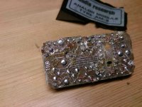
So without much luck etching the epoxy away I went at the module with a chisel. Pretty radical, and the module is wasted, but I was able to reverse-engineer the most important part, and now I can build two new ones, so it was the right decision.
At the same time it allows me to share my results with you dear DIY'ers.
I even found that some of the transistors still carried their type, so now I even bought the correct types for the rebuild.
Anyway check out the attached images and the schematic.
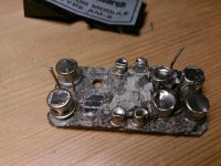
All the 369 ohms transistors ( R1-R4 and R7-R10) were on the same resistor array, with a couple of them still working so I could measure them. Unfortunately I cannot determine the 'small' transistors, as well as some of the resistors. R5 and R6 might even be zeners but they were chisel'ed away, together with the connections between the points (there was some loose ends of copper-threads sticking out of the residue here and there).
So a complete schematic it is not. However it is perfectly clear, that it is a Jung-buffer like the output-stage, just as I presumed.
And despite the missing connections it should be possible to recreate a circuit that performs just as well by redesigning the current generators.
Does anyone have suggestions?
You are more than welcome.
So without much luck etching the epoxy away I went at the module with a chisel. Pretty radical, and the module is wasted, but I was able to reverse-engineer the most important part, and now I can build two new ones, so it was the right decision.
At the same time it allows me to share my results with you dear DIY'ers.
I even found that some of the transistors still carried their type, so now I even bought the correct types for the rebuild.
Anyway check out the attached images and the schematic.
All the 369 ohms transistors ( R1-R4 and R7-R10) were on the same resistor array, with a couple of them still working so I could measure them. Unfortunately I cannot determine the 'small' transistors, as well as some of the resistors. R5 and R6 might even be zeners but they were chisel'ed away, together with the connections between the points (there was some loose ends of copper-threads sticking out of the residue here and there).
So a complete schematic it is not. However it is perfectly clear, that it is a Jung-buffer like the output-stage, just as I presumed.
And despite the missing connections it should be possible to recreate a circuit that performs just as well by redesigning the current generators.
Does anyone have suggestions?
You are more than welcome.
Attachments
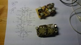
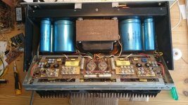
all-right: Long time no progress, but here we go:
At wintertime I chisseled the non-working AM-1 module and did as much reverse-engineering as possible, and it is definitely possible to recognize the topology and recreate a replacement circuit. (See bmp file)
Last week I finally also got around finishing up a replacement module ( not 100% accurate but it works as intended), and ofcourse I made two modules and pulled out the working AM-1 module ( any takers?)
The amplifier now works and plays wonderfully.
Enjoy images and shoot any question.
Attachments
- Home
- Amplifiers
- Solid State
- How to fix the Audio Research D-110 modules