Hello
I am looking for a voltage controlled resistor, with floating terminals, so that I may experiment with building a compressor circuit. Of course I could walk to the shop, pay 70-150 pounds and buy the best compressor guitar pedal, but where's the fun in doing that.
Being it that I am trying to string the circuit together with a couple of transistors, I am looking for something equally simple. For example NOT an LM13700, or other IC which does the job (I might as well go buy the ready made pedal then).
So my theory is rectify the input signal, similar to a peak detector, then use it to control a voltage controlled resistor which is placed strategically somewhere in a feedback loop, or maybe shunt a RE or RC.
I have experimented with using an FET and while it works, it provides very little control and is not flexible, in that it only works under a strict set of circumstances, anything else and it fails (lots of distortion etc). The FET is great for on-off, but the bits in between are very hard to control properly, it even distorts on one side of the waveform.
So I am looking for something else. I have not tried the LED-->opto-thingy yet, but what I am looking for is some simple technique involving standard parts.
I have also looked at some circuits but many are extremely complicated, it is like looking at (CPU) code which works by side-effect (for example using an "ADD" instruction not for "adding" but because "ADD" happens to do something to some flag somewhere, this sort of thing).
So to repeat my approach is simple: rectify the input signal (this is easy), get some voltage with controllable attack and decay (also easy) and then try to use this voltage in a creative way so that over a threshold it starts to attenuate the input signal.
Any ideas welcome.
akis,
There are only two or three "low-level" ways that I found, which are: the FET, the Vactrol-type LED-->photosensitive resistor, and maybe the digital potentiometers. I always ended up using the Vactrols. But they are non-linear in their response so you would need a feedback control loop.
Regarding the "peak detector" part, what you would want is called an "envelope detector". A true peak detector's output never goes back downward, unless reset. An envelope detector includes a resistance in parallel with the capacitor that stores the peak voltage, so that the detector can also follow downward-trending amplitudes. The trick is in choosing the C and R values that will follow the range of envelope frequencies fast enough and well enough, but not so fast that the underlying signal produces artifacts in the output. [For cases where a very fast and fast-settling response was required over a relatively large range of frequencies, I have had to use a variable (voltage-controlled) resistance in parallel with the detector's capacitor.]
You would probably also want to use an "ideal diode" type of rectifier circuit, so your circuit could detect all the way to zero volts, instead of having to stay a diode drop away from zero. You might actually want to full-wave rectify (instead of half-wave) and then take the absolute value, so you'd be working with both the positive and negative peaks. In that case, too, you'd probably want to use an opamp/diodes "ideal rectifier" circuit. See the AN-20 and AN-31 Application Notes, from http://www.national.com, along with others, for basic opamp circuits. And there are also several pretty-good "envelope detector" circuits available on the web, findable through Google searches.
LTspice is very nice for simulating circuits like this, since it also allows you to use WAV files as inputs (and outputs). It's a free download from Linear Technology - Linear Home Page .
Cheers,
Tom Gootee
I have experimented with using an FET and while it works, it provides very little control and is not flexible, in that it only works under a strict set of circumstances, anything else and it fails (lots of distortion etc). The FET is great for on-off, but the bits in between are very hard to control properly, it even distorts on one side of the waveform.
There is a lot of literature showing how to properly implement a VCR with JFETs. There is a basic linearisation technique (feed half the drain voltage to the gate) which must be applied for reasonably linear operation; also the proper parts choice is important--you want high Vp (e.g. a J111).
More advanced techniques include bootstrapping to further increase linearity (at the cost of noise) and the design of a fully floating VCR.
The opto-resistor approach however is surely easier to understand and implement.
Samuel
Hi,
That is what I meant, I have a pot in series to the reservoir cap (attack) and one in parallel (decay), but the following circuitry also has its own demands on the cap, so it discharges easily. Once in full operation i will tinker with the various R/C constants.
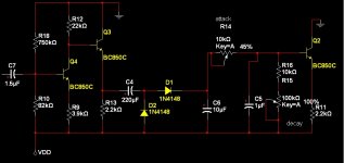
The input signal is amplified, then rectified, and then buffered by a transistor - so the outpout voltage fluctuates between X and (X+d). This (X+d) range will form my "control vlotage" with which to limit the gain of an unrelated stage to effect a compressor. If I want to increase d then I can increase the gain of the amplifier or vice versa. I can control the "attack" and the "decay" with pots.
I have ordered some light sensitive resistors, I will tinker with those and see what happens.
*******
The big problem I have had with the FET is that at a point half-way in its range it is affected badly by the variation of voltages between D and S, regardless of what's on the gate. A resistor would present same resistance, regardless the voltage across it. I have played with a number of variations of US5175508, basically using a FET in the feedback loop, but surrounding it with a resistor network to control the min/max gain.
I have also tried a bridge in the feedback loop (I copied a schematic from somewhere), and had similar issues as with the FET.
********
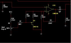
In the attached circuits I have used op-amps but for the final circuit they will be replaced by discreet components, so in the end there should only be a handful of transistors in the whole circuit.
That is what I meant, I have a pot in series to the reservoir cap (attack) and one in parallel (decay), but the following circuitry also has its own demands on the cap, so it discharges easily. Once in full operation i will tinker with the various R/C constants.
The input signal is amplified, then rectified, and then buffered by a transistor - so the outpout voltage fluctuates between X and (X+d). This (X+d) range will form my "control vlotage" with which to limit the gain of an unrelated stage to effect a compressor. If I want to increase d then I can increase the gain of the amplifier or vice versa. I can control the "attack" and the "decay" with pots.
I have ordered some light sensitive resistors, I will tinker with those and see what happens.
*******
The big problem I have had with the FET is that at a point half-way in its range it is affected badly by the variation of voltages between D and S, regardless of what's on the gate. A resistor would present same resistance, regardless the voltage across it. I have played with a number of variations of US5175508, basically using a FET in the feedback loop, but surrounding it with a resistor network to control the min/max gain.
I have also tried a bridge in the feedback loop (I copied a schematic from somewhere), and had similar issues as with the FET.
********
In the attached circuits I have used op-amps but for the final circuit they will be replaced by discreet components, so in the end there should only be a handful of transistors in the whole circuit.
Attachments
The big problem I have had with the FET is that at a point half-way in its range it is affected badly by the variation of voltages between D and S, regardless of what's on the gate.
As I said: you need a JFET with high Vp. 2N5116 is a poor choice. And then you should minimise voltage swing across the JFET--attenuate signal before it, amplify afterwards. Or use a bootstrapping technique. Both approaches increase noise, nothing to be done about that. There's a reason why people started to design complicated and expensive VCAs based on bipolar translinear gain cells.
Samuel
Hi,
That is what I meant, I have a pot in series to the reservoir cap (attack) and one in parallel (decay), but the following circuitry also has its own demands on the cap, so it discharges easily. Once in full operation i will tinker with the various R/C constants.
The input signal is amplified, then rectified, and then buffered by a transistor - so the outpout voltage fluctuates between X and (X+d). This (X+d) range will form my "control vlotage" with which to limit the gain of an unrelated stage to effect a compressor. If I want to increase d then I can increase the gain of the amplifier or vice versa. I can control the "attack" and the "decay" with pots.
I have ordered some light sensitive resistors, I will tinker with those and see what happens.
*******
The big problem I have had with the FET is that at a point half-way in its range it is affected badly by the variation of voltages between D and S, regardless of what's on the gate. A resistor would present same resistance, regardless the voltage across it. I have played with a number of variations of US5175508, basically using a FET in the feedback loop, but surrounding it with a resistor network to control the min/max gain.
I have also tried a bridge in the feedback loop (I copied a schematic from somewhere), and had similar issues as with the FET.
********
In the attached circuits I have used op-amps but for the final circuit they will be replaced by discreet components, so in the end there should only be a handful of transistors in the whole circuit.
I know this is an old thread but I wonder what happened with your idea.
Long time ago I started designing and building an LDR based stereo dynamics processor. It´s not perfect yet but the compressor part works great.
if you looking for circuits: Silonex, Thatcorp
VCR with Silonex
VCA with Thatcorp
thx my circuit just needs some finetuning.
Actually it's not just an opto compressor like all those relatively simple schematics we see everywhere, it can also expand the audio before the compression hits in. Once adjusted, this will help to reduce noise and prevent the compressor from pumping and/or breathing.
It's my own design, took me more than ten years to create this device.
VCAs were never an option because these distort the signal when driven hard with a very short attack and release time (talking about up to 40 dB of gain reduction). Vactrols have their own time constant, so these will never clip the signal like a VCA would do with an attack time near zero.
I use this beast to protect my amp, speakers and the neighbours.
However, if someone's interested I can share the compressor schematic.
")


- Status
- This old topic is closed. If you want to reopen this topic, contact a moderator using the "Report Post" button.
- Home
- Amplifiers
- Solid State
- Voltage controlled resistor