I posted this on AudioKarma with no luck of help
Hi All
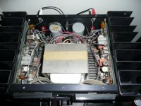
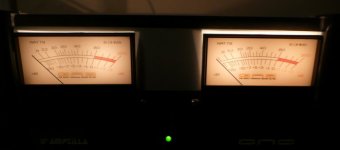
I just got a Son of Ampzilla, it was playing fine then it just started to buzz the right side and pegged the r.side meter? I had the cover off because when I got it, something was rattling around in there,I found a penny (the guy I got it from must have had kids) but after it started to buzz I found another one in there but it didnt look like it was shorting anything. Anyone have any ideas? I'm going to test the caps and go from there. Anyone have the bais points and settings?
Thanks, Roy
I was messing with the adjustment on the front of the meter to get it to 0. But I don't think that caused the problem. So far I tested the OPT all good (4) tested the drivers all good, tested the caps with a Blue esr meter all looked good. and just poked around and didnt see anything burned. When pluged in it pegs the r.side meter but i instantly turn off.
Roy
Hi All
I just got a Son of Ampzilla, it was playing fine then it just started to buzz the right side and pegged the r.side meter? I had the cover off because when I got it, something was rattling around in there,I found a penny (the guy I got it from must have had kids) but after it started to buzz I found another one in there but it didnt look like it was shorting anything. Anyone have any ideas? I'm going to test the caps and go from there. Anyone have the bais points and settings?
Thanks, Roy
I was messing with the adjustment on the front of the meter to get it to 0. But I don't think that caused the problem. So far I tested the OPT all good (4) tested the drivers all good, tested the caps with a Blue esr meter all looked good. and just poked around and didnt see anything burned. When pluged in it pegs the r.side meter but i instantly turn off.
Roy
Connect your meter to the output binding posts and check for DC on the output. Since the meter pegs I'm assuming there's DC. Do you have a schematic? If you do check the zener regulated supply. If that's bad the DC offset adjustment won't work and any offset in the front end will be amplified thru the amp. The main power supply is common to both channels so that is probably OK. You've checked the OPTs and they would blow fuses if they were bad. It might even be a bad/dirty DC offset trimmer, try moving it stop to stop to clean it up and then put it in the middle, turn it on and try adjusting for zero DC at the binding posts. The DC offset trimmer is the upper most trimmer on each board. The two towards the end of each driver PCB are for adjusting the VI limiters. The trimmer on the OPT PCB, the lower board, is for adjusting idle current. That is 30mv across one of the .2 emitter resistors. Make sure the input is shorted to gnd before adjusting anything. One caution using a ESR meter if you have a shorted capacitor it will look like a really good capacitor. Though shorting is not the usual failure mode for a capacitor it does happen.
Craig
Craig
I do have a schematic but don't know what and where the zener regulated supply is and how to test it. I'm a fast learner and know I can fix the amp with your and others help. Thanks!
The pic's of the meters was taken before it all went bad.
One thing, is , this was the best sounding amp I ever had!!! and I only had it going for about an hour.
Roy
The pic's of the meters was taken before it all went bad.
One thing, is , this was the best sounding amp I ever had!!! and I only had it going for about an hour.
Roy
Attachments
Does sound like DC on the output.
Disconnect the Vu meter if you decide to re-power it again. The DC will blow it out. Are you sure you checked the correct channel outputs for shorts with your VOM? If yes then you probably lost a power supply rail. Don't connect any load (speaker or otherwise) until you get the DC on the output problem fixed. It should be less than .05 Volts DC.
If you've got one side working, you should be able to make comparative checks with your VOM and fix the other side.
Sometimes you'll find semiconductors several stages back shorted and all will have to be replaced.
The power supply consists of two 'rails', one providing a positive voltage, the other a negative voltage with respect to ground. In addition, there is another supply riding on top of the rails which slightly boosts the voltage for the input and driver stage--this isn't often done on most amplifiers.
The supply voltages are plus and minus 45 volts DC for the output transistors and plus and minus 51.6 volts for the driver stage; there should be very little measurable AC ripple. Since you've got a big DC offset, I think there's a bias problem.
I've got a SOA here to fix which has a bias problem in one channel--goes to Class C and audibly distorts. Haven't figured it out yet; I'm hoping it's not the bias IC which is hard to replace. In my unit the input different amplifier transistors are socketed; those should be checked and carefully replaced--there's a slight chance one could have loose/dirty connectors or be defective.
You can check all four output rail voltages at the fuses on the power supply PCB, +45 and -45 VDC, on both left and right sides of the board. Be sure to check both sides of the fuse in case you don't know which is in or out. The input rail voltages, + and -51 VDC, can be checked at the 10 Ohm resistors right next to the double ceramic capacitors, .1uf, on each upper corner of the drive boards.
Craig
Craig
Can I pull the fuse's F001 -45v, F002 ch B, F003 ch B, F004 +45v then check the volt's or do they have to be in? What I read looks like out is fine (check both sides of fuse..) and if its higher or lower I will report what I find. I'm just gun shy to smoke the amp.
I'm still at work but will try this when I get home
Roy
I'm still at work but will try this when I get home
Roy
If you pull them you'll only be checking the power supply which is fine though it will unloaded. If the voltages check OK that way put the fuses back in and check again, they all should be a hair lower now with a load on the supply. The fuses only protect the driver and output stages so you could still have a input/VAS power supply problem even if those voltages check OK. You can check the zenered supplies at R104 and R125, the 2.2K 1/2W resistors by the double ceramics I mentioned earlier, should be + and - 28VDC.
Craig
Craig
Well.. I found that R101 10ohm 1/4w was bad. All I had was a 1/2w so I put it in and now its playing!!!! I got the dc out of the speaker outs down to .44mv but I think I might replace the v.resistor's (there acting funny) do you know the value? I can't read the schematic on that one.
So you were missing the negative voltage to the input/VAS stage, that would cause massive DC offset and the DC offset wouldn't work either. The value of the offset trimmer is 1KOhm. The VI trimmers are 500 Ohms each and the bias trimmer is 500 Ohms also in case you get ambitious. Now the hard part, why did it go open. Can you measure voltage across each of the 10 Ohm resistors, the voltages should be the same. If the voltage across the one you replaced is larger you still might have a problem. Let's see what the voltages are and go from there.
Craig
Craig
the bad resistor read 200+k ohm's so yes it was blocking the voltage. Now it reads 49v one side 49.6v (the bad one was towards the back of the amp) same on the other 10ohm (towards the front). The side I'm working on does seem warmer then the "good side". Its been rock'n out for over an hour now and the voltages look good.
 Here's a pic, this is a wonderful sounding amp.
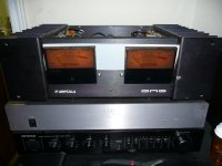
All four of the voltage drops are the same now across the 10 Ohm resistors? Then I guess you fixed it. As far as the warmth goes check the idle current on both channels, 30mv (.03)VDC across one of the emitter resistors (big cement jobs). Make sure the inputs are grounded before setting bias or offset. Now I need to get off my butt and finish mine.
Craig
Craig
- Status
- This old topic is closed. If you want to reopen this topic, contact a moderator using the "Report Post" button.
- Home
- Amplifiers
- Solid State
- Son of Ampzilla BUZZ