Vargas is correct.
A flat surface is better at transferring heat from one device to the other.
Why?
Because a non flat surface mating together with another flat surface will leave gaps in the metal to metal contact interface.
The "gaps" can be scratches or much worse. Those gaps if filled with air act as insulators (= high thermal resistivity).
Polishing both surfaces of the Thermal interface can reduce the "gaps" and will result in less thermal resistance.
The requirement for best thermal conductivity is reduction of the "gaps" to as near zero thickness as possible over the largest area as possible.
Why do we use thermal compound in the thermal interface?
To reduce the thermal resistivity of the "gaps". Thermal compound should have much better conductivity than air.
For this to be effective, the "gaps", all of them, must be completely full of thermal compound. In addition the metal to metal contact must still be made between the "gaps". That is why we should use the minimum of thermal compound to just fill the "gaps" completely, but not separate the metal interface from that necessary metal to metal contact across the biggest area possible.
If we introduce an electrical insulator between the two metal surfaces. Then we now have three layers to consider. The hot device to insulator interface, the thickness of the insulator and the insulator to cool device interface.
That three layer thermal path explains why a thermally filled metal to metal interface conducts heat better than any of the insulated interfaces.
Emissivity is a completely different subject.
Last edited:
But a word, or several, of warning.
A flat scratched surface may be better than a polished version of a non flat surface.
It depends on how much of "non-flatness" exists in the polished version compared to the (alleged) flatness of the scratched surface. The polishing can be the process that introduces the non-flatness from the previously flat scratched surface.
Because it is not easy to obtain a flat surface and not easy to have it polished
then we use silicon grease, the thermal compound fill all the gaps resulting in a better heat transference... flat or not that flat.... polished or not polished...then you gonna have much better results when you compared with the transistor attached to the heatsink without any kind of thermal compound.
In other words dear Juan...having polished surface or not having a polished surface...always use thermal compound, and to avoid air bubbles inside, apply a lot and let the excess appear around the component after you tight your screws... remove the excess with cotton tissue, clean the white marks (stains from your silicon grease) with a cloth dampened in Kerozene (Querozene) or aviation fuel...or any kind of petrol solvent and be happy.
regards,
Carlos
Last edited:
and flat shiny smooth trumps flat matt smooth. Matt being very fine scatches.The contact surface must be flat, as AndrewT stated, flat trumps shiny smooth.
On the other hand for bolted interfaces the thermal impedance increases significantly with distance from the fasteners, yes thermal fillers help mitigate this problem.
If you imagine a curved TO-3 package such that the center point touched the heat-sink prior to the mounting ears, then when the TO-3 is fastened down flat, the center area will have more pressure (less thermal impedance) than it would having it started out flat.
Similarly scratched interfaces surfaces with the scratches being perpendicular to each other when fastened together will cause the crossing of the scratches to form lots of very good thermal interface points kind of like local welding.
Thanks
-Antonio
I don't know, but the extra pressure from tighter fastened bolts does seem to improve the thermal flow. That could be due to deformation of the metal to metal points becoming wider areas under the extreme pressure of point to point contact....................Similarly scratched interfaces surfaces.............when fastened together will cause the crossing of the scratches to form lots of very good thermal interface points kind of like local welding.............
But that deformation of the points must not be allowed to change the shape of the flat surface. This is may be why clamping gives good results, rather than bolting.
The dual bolts of the big Sankens and the To3 packages may also explain why they perform well. They are closer to being "clamped" rather than a single bolt that is way off centre from the hot spot under the hot junction.
Last edited:
Think of heat energy as being similar to visible light energy,
metalic shiny surface will refelct it and absobtion isnt optimal,
Here surface area and mounting pressure are important, but the overall colour of the heatsink is also a big factor.
As for the mating surfaces, these will Never be 'flat' no matter how good you are at diy, thermal paste works a dream cure for this,
Ill even say that very minor scratches on a flat surface will have minimal inpact, if proper amount of paste vs mounting pressure is adhered to.
Ill use a matt black rippled fin heatsink over a shiny gold or shiny anodized heatsink.
" Shiny gold anodised heatsinks might look great (if you like that sort of thing), but are hopeless at radiating heat. It's no accident that the radiator in a car, or the condenser on the back of a refrigerator is matte black - not chrome plated and shiny. Matte black heatsinks are the best for radiation"
ESP - Heatsink design and transistor mounting
is it possible to paint the heat sink in a matte color using high temperature paint Vostro? because having the aluminum polished create problems because is extremely sensitive to scratches even with you bare hands the dusty environment where I live here in Puerto Rico, also Puerto Rico is really humid too and the aluminum can get rusty I use "mother brand" that protect the metal from rust but it can be paint?
Regards
vargasmongo3435
Regards
vargasmongo3435
I think its been noted that the last few posts are dealing with the mating interface and not radiative thermal transfer.
Agreed thermal grease or a filler pad really works wonders, my measured best is from lightly abrading the surfaces to provide contact centers (perpendicular scoring) and remove any oxide, thorough cleaning, then immediately applying the grease or filler pad and fastening the component using a spring washer(s).
Flatness is important as is the roughness of the finish, but keep in mind that if you dont apply pressure you get a theoretical 3 point contant (metal to metal) as pressure is applied the highest point contact is flattened and now an additional contact is made, this continues as a function of the pressure, material hardness and finish.
Thanks
-Antonio
Hello guys! has anyone try this volume control circuit?
Regards
vargasmongo3435
I can tell you that too much noise on this chip.
LM4610 much better.
Hello guys!
I finally have my Supercharged in stereo! weeeee, I having a problem with the other channel "not the board" the board was bias perfectly, it was just a simple 3.5mm cable that was faulty, I replace it and nice dude........ lol good sound guys, I don't have the enclosure yet but I will soon, ok guys take care I will continue on mister Carlos new project Dx Super A layout bye bye.
Dx Blame MKII Supercharged Stereo in Puerto Rico - YouTube
Regards
Vargas
Last edited:
Thank you dear Juan
Nice video, despite the camera audio recording does not help.
Install your speaker in a wooden panel to avoid losses..at least a wooden panel, even a cardboard panel (thick one) will reduce losses.
regards,
Carlos
Nice video, despite the camera audio recording does not help.
Install your speaker in a wooden panel to avoid losses..at least a wooden panel, even a cardboard panel (thick one) will reduce losses.
regards,
Carlos
Attachments
Last edited:
The reason I didn't have sound on the other channel lol
Dx Blame Supercharge Stereo faulty cable - YouTube
Regards
Vargas
Dx Blame Supercharge Stereo faulty cable - YouTube
Regards
Vargas
Juan told me that he has some boards left
He made his own Supercharged pcboard design, almost the same as Mitchel has made and he ordered too many..he has boards left.
So, if you want boards from this multimodel amplifier contact him directly:
vargasmongo@gmail.com
Boards he has are to these amplifiers you see here:
DX Blame Amplifiers - Carlos Mergulhão
regards,
Carlos
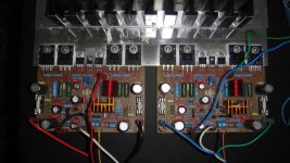
Here is the results of many days working on both boards, I have a few boards left after this I will not order anymore so last time sale. if interesting please contact me at vargasmongo@gmail.com note: this board is fully tested for about a few months and no problems at all.
Regards
Juan
Regards
Juan
Attachments
")
- Status
- This old topic is closed. If you want to reopen this topic, contact a moderator using the "Report Post" button.
- Home
- Amplifiers
- Solid State
- Are you ready to face strong emotions?.. Dx Blame MKII and the Supercharged release!