Here you have another "style" of adjustment
Follow this link, please:
YouTube - Adjustment option to the Supercharged - English and Portuguese
regards,
Carlos
Follow this link, please:
YouTube - Adjustment option to the Supercharged - English and Portuguese
regards,
Carlos
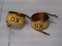
Internal diameter - 5 milimeters
External diameter - 7 milimeters
Wire diameter - 1 milimeter
Coil length - 17 milimeters
Number of turns - 15 plus half and plus half...this represents 16 turns
Inductance - aproximatelly 0.692 microhenries (692 nanohenries)
Resistance in paralel was increased to 15 ohms, 18 ohms or 20 ohms / 5 watts... can be a coiled wire resistance.
During tests i have used the coiled wire resistance of 18 ohms and 5 watts...some inductance is provided by the resistance windings.
Blue boards have holes into the coil position, that accept 1 milimeter coil wire without problems.
regards,
Carlos
my coil just recently made

Attachments
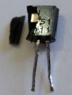
ATTENTION please!.... first VAS emitter resistance increased
back to Doctor Self original value.
By the first time i had a transistor burned, was a ground disconnected from an active filter that produced huge hum... the transistor exploded... first time...but seems the resistance should be increase.
Some folks have said that...but real life test have not proved to me that need, nor simulator and nor calculations...but now, no doubts must be increase to 1K or even bigger value.
Only the first VAS, the 2N5551 was destroyed... this resulted in an open circuit there, i had huge off set and speaker fuse have protected the speaker... after replacement all worked fine
regards,
Carlos
Attachments
Hi,
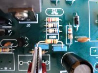
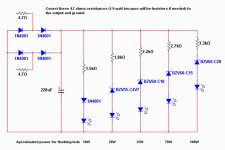
it would be better to add a collector resistor rather than increasing the emitter resistor.
Increasing the emitter resistor increases the degeneration of that transistor and reduces the gain of that stage.
Adding a collector resistor has the effect of reducing the working Vce of the transistor and has very little effect on the amplification of the stage. Ost chose a very low value of collector resistor (220r) because the simulator told him that gave the least effect on distortion.
I think it can go upto 1k to 2k with little if any effect on the sound.
When the fault condition occurs the Vce drops massively to reduce destructive power in the transistor. A larger value of collector resistor provides more protection. But it must remain small enough in normal operation that the transistor has adequate Vce to amplify as intended.
back to Doctor Self original value.
By the first time i had a transistor burned, was a ground disconnected from an active filter that produced huge hum... the transistor exploded... first time...but seems the resistance should be increase.
Some folks have said that...but real life test have not proved to me that need, nor simulator and nor calculations...but now, no doubts must be increase to 1K or even bigger value.
Only the first VAS, the 2N5551 was destroyed... this resulted in an open circuit there, i had huge off set and speaker fuse have protected the speaker... after replacement all worked fine
regards,
Carlos
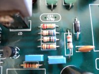
Back when I designed my clone , I had my "first VAS" get warm after clipping for long periods in the "doghouse" . It never let out magic smoke , but something had to be done to make it "bulletproof" (below). With 680R = E / 220R = C , 45V rails tests could not even get the device warm and my original specifications were preserved. I can't test for 75V rail clipping (too much for my load), but all devices stay cool even with heavy use.
Don't feel bad , I smoked a few trannies ... oscillated with wrong resistors , even put a device in backwards.
We live and learn !OS
Attachments
Allright Ostry..thank you.
I am suggesting Supercharged builders to use a small heatsink to the second VAS..i have increase the first VAS emitter resistance to 1K (Dr. Self original blameless value)...and people can cut a small piece of thin aluminium foil (0.5 milimeters thick) to fix into the MJE15032/15030 or other model from this series)
A hell transistor these ones...well, at least the ones i have are very different in gain.... PNP is twice the gain of the NPN....grrrrrrr!
YouTube - DIY mini heatsink for VAS
regards,
Carlos
Playing with flashing leds and informing last and final modifications to the
Supercharged....
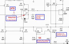
Gain resistance (R13) was decreased to 470 ohms in my home to match the satelite receiver...original is 1K...it is in series with the 330/470uf electrolitic...but i found much better to use 100uf..sound was more precise, more clean...better!...i found 470uf there sounding undefined...bass loss the punch...was strange.
Also here you have the flashing leds toy:
http://www.youtube.com/watch?v=1R4RLM6wFBYMore youtube links to come soon.
regards,
Carlos
Supercharged....
Gain resistance (R13) was decreased to 470 ohms in my home to match the satelite receiver...original is 1K...it is in series with the 330/470uf electrolitic...but i found much better to use 100uf..sound was more precise, more clean...better!...i found 470uf there sounding undefined...bass loss the punch...was strange.
Also here you have the flashing leds toy:
http://www.youtube.com/watch?v=1R4RLM6wFBYMore youtube links to come soon.
regards,
Carlos
Attachments
I have made some tuning in the Supercharged
YouTube - Final video about modifications made into the Supercharged
Some issues about the "L" adaptor i am using...the metal is no good to heat transference:
YouTube - Supercharged L adaptor heat transference issues
regards,
Carlos
YouTube - Final video about modifications made into the Supercharged
Some issues about the "L" adaptor i am using...the metal is no good to heat transference:
YouTube - Supercharged L adaptor heat transference issues
regards,
Carlos
Member
Joined 2009
Paid Member
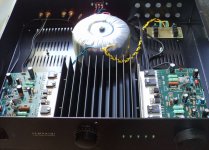
I don't have sound on this computer, but I looked at the video and saw an L bracket mounted to the end fin of the heatsink - which isn't the best option. The heat from the bracket will flow to this thin fin only - the bracket needs to be mounted against the spine, the thick back plate of the heatsink that the fins are all joined onto.
Member
Joined 2009
Paid Member
Ah yes, well the fun can be in the challenges of these things. I'm not sure what constraints you have, whether perhaps you can make some other changes or additions to this arrangement such as trying to provide more thermal coupling from the L bracket to the 'backplane' of the heatsink or adding another heat-spreading bar down one side of the heatsink etc.
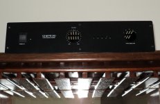
I just had to make this way because the enclosure
because of enclosure height i have to lay this heatsink in the enclosure bottom alike a bed... laying down.... enclosure is not "tall" enought, has not room to fix this heatsink in the correct convection position... say...placing fins in the vertical position
Then i had two main options to decide.... or to saw the heatsink in two parts or to install the way you see with the heatsinks layed down over my bench.... the base will be fixed into the enclosure bottom..fins pointing up (this is fine) and fixing into the fins... you know bigun...home made, not industry made...we do what we can and sometimes we do not obbey the rules, or tradition... sometimes we cannot have the best solution... then you have to decide...or you adapt to use what you have or you give up to build...i use to adapt.
All my life i had to improvise... i have not that "corporation" as i use to say...it is DIY...home made things.... if i cannot do in the correct way, then i try another less correct way...will be always the correct way to me...as in my mind..not to stop because obstacles is a rule.
regards,
Carlos
Last edited:
in the UK we have a saying that means much the same "peeing against the wind"....as in my mind..not to stop because obstacles is a rule.
There comes a point when the odds are stacked against so highly that no compromise that is left is capable of being "good". At some point one moves into the territory of "bad".
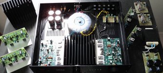
Here you have Bigun....not a very good idea but i could use
the enclosure i could find.
I am just starting....studying positions and cables...anything interconnected...just posted in place.... the filters was missed and some details..i am still waiting knobs from China, and input golden RCA.
This one is to my own use....usually i build to myself or family... sometimes to special local friends...these ones you know 30 years long.
Heatsinks..home made:
http://www.youtube.com/watch?v=nDsyEsZ0HFw
regards,
Carlos
Attachments
Last edited:
My transformer is a 550 watts unit....so, i can produce 370 watts of audio
draining full power from this transformer....but i will use 8 ohms...so, it will put out 100 to 130 watts rms to each channel.
Filters are only 30 thousand plus 30 thousand microfards to another Supercharged...this one will have only 20 thousand plus 20 thousand.
I have another 2 cases. one for another Supercharger (boards already assembled and tested), and the third one will go to a Dx Blame ST (brazilian green boards... i still have tob find another fourth enclosure to the Dx Blame ES (board assembled and tested) the one without " L " adaptor.
regards,
Carlos
Attachments
Last edited:
Member
Joined 2009
Paid Member
I've struggled myself with these challenges - my BotchUp project was canned because it got too hot. Anyhow, I think you can improve the L bracket approach by turning the bracket upside down so that the part of the bracket that is bolted to the heatsink runs downward to the bottom of the heatsink assembly and helps transfer heat directly the backplane of the heatsink.
People needing long conversations, big questions or things alike
please, go to my direct email adress:
nanabrother@hotmail.com
Because in our forum messenger system i cannot attach images (only links) and audio messages...so....not good enougth.
regards,
Carlos
please, go to my direct email adress:
nanabrother@hotmail.com
Because in our forum messenger system i cannot attach images (only links) and audio messages...so....not good enougth.
regards,
Carlos
Supercharged, more fine tuning!
See this video please:
YouTube - Tinkering the Supercharged - more fine tuning
regards,
Carlos
See this video please:
YouTube - Tinkering the Supercharged - more fine tuning
regards,
Carlos
- Status
- This old topic is closed. If you want to reopen this topic, contact a moderator using the "Report Post" button.
- Home
- Amplifiers
- Solid State
- Are you ready to face strong emotions?.. Dx Blame MKII and the Supercharged release!