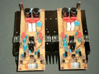
Nice work. For those of you who don't know: Sonny's connectors is really esoteric.
It's Wago!
With these connectors you will get almost tube sound. I use them also but model 255 and 256 with levers. You know I'm kidding? But Wago is really good in industrial environment.
Sonny, have you tested yet to use "current gain" in the current mirrors?
It's Wago!
With these connectors you will get almost tube sound. I use them also but model 255 and 256 with levers. You know I'm kidding? But Wago is really good in industrial environment.
Sonny, have you tested yet to use "current gain" in the current mirrors?
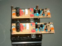
sonnya said:and the last one.
Well done Sonnya! I like the color coded connectors, they show you really did pay attention to the details. QA people love this, it decreases chances of errors.
Did you already publish the schematics? I might have missed them.
peranders said:[snip]With these connectors you will get almost tube sound. I use them also but model 255 and 256 with levers. You know I'm kidding? But Wago is really good in industrial environment.[snip]
Aha? You mean these connectors introduce harmonic distortion and freq response deviations?
Jan Didden
It's Wago!
With these connectors you will get almost tube sound. I use them also but model 255 and 256 with levers.
I like them as well, sometimes I even use them on veroboard prototypes (simply for convenience).
They are widely used for industrial applications also in Switzerland.
Regards
Charles
janneman said:
Well done Sonnya! I like the color coded connectors, they show you really did pay attention to the details. QA people love this, it decreases chances of errors.
Did you already publish the schematics? I might have missed them.
Thanks, it is a lot easer not to make any mistakes.
No i haven't not before all tests have finished. including listening tests..
Sonny
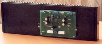
With a 2 * 30VAC / 300VA i get +/-43VDC.
I should be able atleast swing to around 38Vpeak so ...
~90W/8 Ohm...
~160W/4 Ohm..
I changed the compensation caps from 2*47pF -> 2*100pF in the gain node...
After this i was able to remove compensationcaps in the CFP outputstage.
Right now it goes from 1.3Hz to 250KHz (-3dB)...
The DC offset is drifting within +/10mV from the setpoint.
Sound!
The mids and highs are very detailed. Especially on voices and high-hats.
P-A,
if I can reply, I do these tests. Not only values you have mentioned, but also caps of 1.5nF, 6.8nF, 15nF, 33nF and your values (100nF, 1uF) and 3.3uF. It is interesting that some designs may have problems for example with 15nF // 8 Ohms combination. I also recommend to check the stability into dummy loudspeaker load.
I have found very helpful to place Zobel (Boucherot) network of some 4.7 Ohms in series with some 22nF directly to the loudspeaker terminals of the power amplifier.
Pavel
- Status
- This old topic is closed. If you want to reopen this topic, contact a moderator using the "Report Post" button.
- Home
- Amplifiers
- Solid State
- CFP amp pics