Hello everyone.
After the recent thread below, there has been interest in seeing how the circuit can be improved. This thread was created so that those not interested in changing the circuit can continue in the old thread.
http://www.diyaudio.com/forums/solid-state/174468-very-best-amplifier-i-have-ever-heard.html
This thread is to discuss improvements in performance, stability, and reliability.
Among the issues which were brought up:
1: The circuit can be unstable
2: Output stage bias has no clear adjustment
3: The topology can be improved
4: The frontend CCS is strange, it is hard to know what it was designed for. A more conventional CCS will be less confusing and more flexible.
5: Frontend rails may have sub-optimal power supply
6: Transistors used don't have adequate voltage specs for the rails
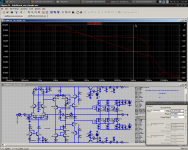
To start, I will offer my thoughts. These are not final, only to give you something to think about. I have attached several files. The first schematic is the original Goldmund amp. The second is the one containing the mods I describe here. The third attachment contains LTSpice simulations of them (where no models could be found for the original transistors, substitutions were attempted). These mods aren't my final word, I vomited them into the simulator at light speed, for lack of time. How to use the simulations: To change test frequency, change parameter "freq" - to change number of warm-up cycles, change parameter "dlycyc" - to change simulated number of cycles, change parameter "numcyc". When performing an FFT, select the same number of points as in the parameter "FFT". If the .MODEL statements are annoying, right-click them and select "invisible". They will reappear the next time you open the file.
Stability
Simulated, the frontend is actually VERY stable, showing textbook curves and well-defined behavior. The issues seem to lie in the output stage.
Output Stage Issues
Firstly, the output FETs have no emitter resistors. Since devices vary widely, and no equalizing force is present, the FETs probably won't share the load equally unless matched by hand.
Secondly, there are not trimmers included in the circuit for output stage adjustment, only one for offset adjustment. We do not know how - or if - the output stage was adjusted at the factory. Adding an adjustment for offset would go a long ways towards making the design more consistent and reliable between builds.
My suggested options for adjustment:
1: Use a trimmer for R20 first, and set bias to a reasonable value. Then turn off unit, measure trimmer and replace with a close value resistor.
2: Install a trimmer permanently, in such a way that a wiper disconnect will not destroy the output stage.
Topology Improvements
The general topology of the Goldmund amp has been seen many times over in the past. Many members of this forum have worked to refine it in their own time over the years, and I am sure many changes might be made.
While we may be tempted to go all-out, this would likely result in the amp being hardly recognizeable in the end. If this is so, why not simply create a whole new amplifier? In this light I would prefer to keep the design "close" to the original. After all, it is my observation that after a few powerful mods have been made, the leftover mods decrease in the ratio of performance gain to price. There is one thing that I suspect is important to the amp's sonic performance. I will copy a post I made:
Secondly, there are two modifications to the VAS which increase performance dramatically.
The transistors of the second LTP don't see an equal Vce, and so aren't balanced, even if they have the same quiescent. Without the second LTP being balanced, the current mirror is more or less for show. MikeB's Symasym cascodes this transistor to ground, and this balances the LTP at no signal. However the best way is to make the Vce's match. In my schematic I do this be cascoding the left transistor to the right's collector. This decreases distortion by a factor of 10, to .003%!
The second mod is considered after seeing Early affect on the lower VAS's linearity. At hundreds of volts Vce variation, it is not a good current mirror. One more transistor helps with this by shielding the mirror from large voltage swings. This brings THD down by a fraction, to .0025%.
CCS
The CCS was made in an odd way. I am not sure whether the designers' concern was noise or temperature stability, but one transistor is turned upside-down and it's B-C junction used as a diode. The behavior of this configuration will depend a lot on the specific transistor used, the originals being the BC182B. The Zener used is a 6V type, and IIRC zeners around this area have the lowest temperature coefficient. If we flip the odd transistor back the "right" way, tempco is fairly low among CCS's, given the two transistors are thermally coupled. This is the way I recommend. The output impedance of this configuration is not very high. However, because the gain of the amp is so high, the voltage variation across it is very low. Because of this, the contribution of the CCS to the overall performance is swamped by larger issues in other parts of the circuit. I don't believe going beyond this will reap great benefits, as far as the numbers go.
Frontend Rails
The frontend rails are constructed using a voltage doubler taken from a 60VAC supply. This results in ~120V rails. OS has described this as a "trainwreck"
Transistor Safety
For the frontend, rails are nearly +-120V. This means that at max power/clipping a transistor may see near 240V. Our transistors should be rated higher than this.
An apt alternative to using high-voltage transistors is to cascode. This way we can use common, familiar parts. In my mod, the MPSA93/43 are replaced by the suitably spec'd MPSA92/42, and output drivers are cascoded.
*catches breath*
Okay, I'm ready.
- keantoken
After the recent thread below, there has been interest in seeing how the circuit can be improved. This thread was created so that those not interested in changing the circuit can continue in the old thread.
http://www.diyaudio.com/forums/solid-state/174468-very-best-amplifier-i-have-ever-heard.html
This thread is to discuss improvements in performance, stability, and reliability.
Among the issues which were brought up:
1: The circuit can be unstable
2: Output stage bias has no clear adjustment
3: The topology can be improved
4: The frontend CCS is strange, it is hard to know what it was designed for. A more conventional CCS will be less confusing and more flexible.
5: Frontend rails may have sub-optimal power supply
6: Transistors used don't have adequate voltage specs for the rails
To start, I will offer my thoughts. These are not final, only to give you something to think about. I have attached several files. The first schematic is the original Goldmund amp. The second is the one containing the mods I describe here. The third attachment contains LTSpice simulations of them (where no models could be found for the original transistors, substitutions were attempted). These mods aren't my final word, I vomited them into the simulator at light speed, for lack of time. How to use the simulations: To change test frequency, change parameter "freq" - to change number of warm-up cycles, change parameter "dlycyc" - to change simulated number of cycles, change parameter "numcyc". When performing an FFT, select the same number of points as in the parameter "FFT". If the .MODEL statements are annoying, right-click them and select "invisible". They will reappear the next time you open the file.
Stability
Simulated, the frontend is actually VERY stable, showing textbook curves and well-defined behavior. The issues seem to lie in the output stage.
I'm never sure where to start when I consider designing an FET amp. Only special amps can drive hundreds of nF's of capacitance gracefully (the amplifier sees hundreds of nF if the capacitance is moved up to the driver stage as in an FET amp), plus there's a bunch of self-resonance and oscillation gotchas to watch out for. It must be hard for a simulator to accurately predict the behavior of a real FET amp.
The high degeneration on the differentials means very low phase distortion, which really helps stability when there is minimal compensation. That is, if you can account for the FETs' nonlinear capacitance. But I have no experience in this realm.
- keantoken
This circuit is also not unstable, barring any disastrous layout choices.
Open loop gain is a conservative 53db [according to simulation], with impressively well-defined HF behavior, thanks to the heavy degeneration. Phase margin is 75 degrees, which is not bad at all.
- keantoken
Jam, it is not unstable, I don't know why you would think that. Without the heavy (75 ohms!) degeneration on both LTPs it might be. See my post:
http://www.diyaudio.com/forums/soli...mplifier-i-have-ever-heard-9.html#post2328755
- keantoken
Hi Keantoken,
I agree that heavy degeneration of the diff. or VAS would help buy there are more factors at play here. We are not talking sims here as they are only a guide.
Question to be asked is how this heavy degeneration could affect the sound?
Regards,
Jam
Ok, I'm not an engineer and have no qualifications, and there's no reason for anyone to listen to me, but in simulation the circuit has very well-defined gain behavior. After billions of hours simulating, I am dead sure that this is almost solely because of the high degeneration resistors, which swamp nonlinear Gm and therefore linearize phase/pulse/HF response. Considering this, the frontend should be VERY stable, it's the power stage that is problematic. Am I right? Does this mean that the oscillation is more a problem with the FETs self-oscillating? It would take a very highly reactive network, like the high-Q stuff that comes from active components near oscillation, to throw the frontend off. Am I right?
- keantoken
Keantoken,
You are on the right track. My main problens were with the output stage. I have built the same amp with different layouts with some being stable and others not. All I am saying it test the board out first before releasing it.
Jam
Nagys,
You are totally off base. Your assumption that if use the same parts the amp will be stable. Well, what about the board material, layout, component spacing and location and list goes on, after all we are talkingf about a high speed circuit here.
[...]
Jam
Output Stage Issues
Firstly, the output FETs have no emitter resistors. Since devices vary widely, and no equalizing force is present, the FETs probably won't share the load equally unless matched by hand.
Secondly, there are not trimmers included in the circuit for output stage adjustment, only one for offset adjustment. We do not know how - or if - the output stage was adjusted at the factory. Adding an adjustment for offset would go a long ways towards making the design more consistent and reliable between builds.
My suggested options for adjustment:
1: Use a trimmer for R20 first, and set bias to a reasonable value. Then turn off unit, measure trimmer and replace with a close value resistor.
2: Install a trimmer permanently, in such a way that a wiper disconnect will not destroy the output stage.
Topology Improvements
The general topology of the Goldmund amp has been seen many times over in the past. Many members of this forum have worked to refine it in their own time over the years, and I am sure many changes might be made.
While we may be tempted to go all-out, this would likely result in the amp being hardly recognizeable in the end. If this is so, why not simply create a whole new amplifier? In this light I would prefer to keep the design "close" to the original. After all, it is my observation that after a few powerful mods have been made, the leftover mods decrease in the ratio of performance gain to price. There is one thing that I suspect is important to the amp's sonic performance. I will copy a post I made:
Wait, I didn't see your last response Jam.
I stated in my last response my observations on the the effect of the degeneration on phase behavior. While they decrease open-loop gain, they linearize phase behavior, at least for the frontend [by swamping nonlinear Gm]. This leads me to think they would improve imaging and soundstage. How they affect other aspects of the sound, I am not sure (hell, I'm not sure of any of this though). Due to the lowered OLG, the distortions of the output stage will be emphasized. This may not seem to be a big problem if the 2SK1058/J49 give benign distortions. If the FET parasitic capacitances are too nonlinear, they may ruin the phase behavior when played loudly.
Of course, it may be more difficult to tell how this behavior will change after the crossover threshold is reached.
- keantoken
Secondly, there are two modifications to the VAS which increase performance dramatically.
The transistors of the second LTP don't see an equal Vce, and so aren't balanced, even if they have the same quiescent. Without the second LTP being balanced, the current mirror is more or less for show. MikeB's Symasym cascodes this transistor to ground, and this balances the LTP at no signal. However the best way is to make the Vce's match. In my schematic I do this be cascoding the left transistor to the right's collector. This decreases distortion by a factor of 10, to .003%!
The second mod is considered after seeing Early affect on the lower VAS's linearity. At hundreds of volts Vce variation, it is not a good current mirror. One more transistor helps with this by shielding the mirror from large voltage swings. This brings THD down by a fraction, to .0025%.
CCS
The CCS was made in an odd way. I am not sure whether the designers' concern was noise or temperature stability, but one transistor is turned upside-down and it's B-C junction used as a diode. The behavior of this configuration will depend a lot on the specific transistor used, the originals being the BC182B. The Zener used is a 6V type, and IIRC zeners around this area have the lowest temperature coefficient. If we flip the odd transistor back the "right" way, tempco is fairly low among CCS's, given the two transistors are thermally coupled. This is the way I recommend. The output impedance of this configuration is not very high. However, because the gain of the amp is so high, the voltage variation across it is very low. Because of this, the contribution of the CCS to the overall performance is swamped by larger issues in other parts of the circuit. I don't believe going beyond this will reap great benefits, as far as the numbers go.
Frontend Rails
The frontend rails are constructed using a voltage doubler taken from a 60VAC supply. This results in ~120V rails. OS has described this as a "trainwreck"
Transistor Safety
For the frontend, rails are nearly +-120V. This means that at max power/clipping a transistor may see near 240V. Our transistors should be rated higher than this.
An apt alternative to using high-voltage transistors is to cascode. This way we can use common, familiar parts. In my mod, the MPSA93/43 are replaced by the suitably spec'd MPSA92/42, and output drivers are cascoded.
*catches breath*
Okay, I'm ready.
- keantoken
Attachments
Last edited:
Keep the slew rate high please
I don't know about amplifier design but please keep the slew rate high (at least 100V/us if possible). Or at least, mention the slew rate of every options that you have because I know some of you will argue about it's audibility.
Keantoken, I was confused with your ASC file because I was expecting 80V for the front end rail but it showed above 110V (I thought I mistakenly changed something). Didn't realize it is a voltage doubler!! (I won't use the original regulator)
But I think high voltage for the front end is also responsible for the slew rate. With higher voltage, you need higher Vce transistor, and with higher Vce transistor usually you will get lower fT/hfe (and higher capacitance), then you will get lower slew rate (or simply "slower" sound)!
So you see that Goldmund has really put the circuit "on risk" to achieve good performance soundwise, by choosing critical transistors in critical operating condition. It is not easy to find replacement for BSS (it has even only 200V of breakdown voltage). It's specified fT for example is 50-200MHz (@Ic=100mA). Typically it is 75MHz but I think Goldmund select the best ones. 2N5551 OTOH is only 150V device and needs paralleling for the same bias current as the Goldmund.
If there is a way of cascoding a 2N5551/5401 to make it possible to operate at high voltage...? My bigger transistor for driver is 2SC3298/A1306B, a bit inferior than the BSS I guess but that is the best one I have. I want to see what transistor you will come up with for the driver...
I am truly amazed , my young friend !! 
Your presentation is very professional , readable and addresses the main issues as they should of been in the "main thread". I didn't bother to do what you did (explain the exact problems) as few were receptive to the obvious issues at hand. I don't feel the zener adds anything musical to the design at all , but some purists would insist on adhering to the original goldmund design.
I hope prospective builders at least read this to avoid a less than ideal DIY experience. VERY well done , Keen.
edit-for the bss_xx use a 2sc4793/2sa1837 pair (Ft 100mhz/hfe 150+/Cob 20p/230v Vce) better than original.
keeping the original in mind , sourcing a second small 60-0-60 trafo might be problematic, suspect the Goldmund had a custom dual winding trafo. A 30-0-30 /50va is EASY to source , at least at Mouser. Using a voltage tripler , since this frontend is just driving the big Cob of the laterals , a compact 100-0-100v source can be made. For both channels , I would expect no more than 60mA per rail.
OS
Last edited:
What is The Power Objective?
I think you need to set the minimum requirement for the power. I believe it is easier to lower the power to achieve maximum sound quality. But how much lower everyone want to go? Or is it just about setting the bias current after final schematic has been decided?? Hmmm... I think it must be decided prior to designing the circuit.
TRANSFORMER
I think 57V secondary (to give 80V rail) is not common. May be a more friendly number should be used. The front end may use additional winding or small transformer.
I am truly amazed , my young friend !!
Indeed, keantoken is very sharp!
I don't feel the zener adds anything musical to the design at all , but some purists would insist on adhering to the original goldmund design.
As long as the newer design address non-theoretical aspects that make an amplifier sound musical, why not? I'm not going to discuss what fuzzy aspects, but I for a moment thought that the resulting mod will only give a better amp on paper. Hopefully not.
The zener is not important imo. Even the topology for the front end can be changed. But if the topology is the same, I'm tired of that SK170. Transistors do not sound the same, that's it. I have K303, K301, K31, K389BL, K369, K246, K247, 2N5457 (and of course K170). They operate differently, so better if the JFET is decided (if same topology is used)
edit-for the bss_xx use a 2sc4793/2sa1837 pair (Ft 100mhz/hfe 150+/Cob 20p/230v Vce) better than original.
OS
Wow, it must be a new product. I hope I can source that.
Thanks OS.
I've gotten another compliment as well. That's funny to me since I threw this together as fast as I could!
As far as slew rate... I'm not sure how to measure it. In the simulator I'm getting about 200V/uS, but that might be optimistic... Judging by the behavior I'm seeing I suspect slew rate will depend largely on PCB design.
Last time I checked, the BSS transistors were 500mA, 500mW devices. The 2N5551/5401 are 600mA, 625mW devices, so if we cascode them like in my second schematic I think we should be fine.
- keantoken
Hi Jay,
Nagys is recommending Hammond transformers for his amps. You can buy them at www.partsconnection.com for approx. 75-90 $ US/pc. Go for the 182 series, 60 VAC. I really don´t know about the exact VA rating but here are a few examples:
Hammond Transformer - More Information Page - 160 VA, 74,24 $ US
Hammond Transformer - More Information Page - 225 VA, 81,92 $ US
Hammond Transformer - More Information Page - 300 VA, 94,72 $ US
Hammond Transformer - More Information Page - 500 VA, 120,32 $ US.
I don´t know if it is possible to finde the above mentioned transformers at a cheaper price somewhere else?
OK, if there is enough interest for this project what about a GB with high quality customized (potted?) transformers?
Karsten
There is also the 2SD669A/B649A to think about, perhaps? These have better specs than the C4793/A1837 IIRC. These can be had from Profusionplc.com. - keantoken
The 2SD669/649 is good sounding driver. I didn't notice it has a good spec. Will check later as I have a few of them as well.
Hi Jay,
Nagys is recommending Hammond transformers for his amps. You can buy them at www.partsconnection.com for approx. 75-90 $ US/pc. Go for the 182 series, 60 VAC. I really don´t know about the exact VA rating but here are a few examples:
Hammond Transformer - More Information Page - 160 VA, 74,24 $ US
Hammond Transformer - More Information Page - 225 VA, 81,92 $ US
Hammond Transformer - More Information Page - 300 VA, 94,72 $ US
Hammond Transformer - More Information Page - 500 VA, 120,32 $ US.
I don´t know if it is possible to finde the above mentioned transformers at a cheaper price somewhere else?
OK, if there is enough interest for this project what about a GB with high quality customized (potted?) transformers?
Karsten
Wow, that's very expensive! I think hammonds are EI transformers. EI transformers sound better imo. But noisy or induce more hum, unless special products are opted, may be.
I have enough transformers but the highest only 40Vac. Eight of them!
Thanks Karsten.
keantoken,
Very well stated.
Maybe now we can come up with a truly outstanding design. As Jay has stated, maybe the first thing to be done is to define the design objectives such as power and bandwidth, followed by details of circuit topology, power supply, front end regulator and choice of components.
I have to admit that I am intrigued by ostrippers (mongrel) output stage but will the use of bipolars here take us too far from our design objective? The other thought I have is to use a better current mirror for the second stage (possibly a Wilson Mirror). Just my two cents.
Jam
Last edited:
hi Kean,
I fully agree on your proposed mods to the orginal Golmund, statements made are loud and clear! And the explanations should be clear for everyone.
Just one question: the FETS are driven by a follower wich is perfect, but do you really need (current sources) Q16/Q18. I think they can be onmitted....
regards,
Piersma
If I didn't have one already , I would go for the "gold" mund...
The" big one" 800VA/ 55-0-55
Antek - AN-8455
The little one (36VA/.75A 24-0-24) , with a voltage tripler (1 more cap/ 2 more diodes)
4900-8048RF65 Tyco Electronics / P&B Transformers

My PS100 CLC power supply with 8 X 8200uF caps (Apex Jr. 3.00 apiece) Radial Capacitors

PS 100 will take any 10mm lead spacing cap as well.(universal)
http://www.diyaudio.com/forums/attachments/solid-state/190907d1286429125-mongrel-supersym-ii-ps100_test.jpg
PS100 on my site or "mongrel thread".
You could build the whole deal for 140+USD 2PS's/ 2 trafo's... everything!!
sure beats spending 250+ !!
OS
The" big one" 800VA/ 55-0-55
An externally hosted image should be here but it was not working when we last tested it.
Antek - AN-8455
The little one (36VA/.75A 24-0-24) , with a voltage tripler (1 more cap/ 2 more diodes)
4900-8048RF65 Tyco Electronics / P&B Transformers
My PS100 CLC power supply with 8 X 8200uF caps (Apex Jr. 3.00 apiece) Radial Capacitors
PS 100 will take any 10mm lead spacing cap as well.(universal)
http://www.diyaudio.com/forums/attachments/solid-state/190907d1286429125-mongrel-supersym-ii-ps100_test.jpg
PS100 on my site or "mongrel thread".
You could build the whole deal for 140+USD 2PS's/ 2 trafo's... everything!!
sure beats spending 250+ !!
OS
I would expect there are a few reasons for omitting the source resistors.
I further suspect that the designers had considered very carefully how to get a resistorless design to work properly.
If we knew what was in their heads we could try to emulate their design.
I reckon the best we can do is guess and accept the risks involved with our guesses.
I further suspect that the designers had considered very carefully how to get a resistorless design to work properly.
If we knew what was in their heads we could try to emulate their design.
I reckon the best we can do is guess and accept the risks involved with our guesses.
Jay wrote:
Hi Jay,
The links I posted are all for toroids - just to let you know. Yes, they might be expensive. I can see that Ostripper has a suggestion for a 800 VA transformer...
Karsten
Wow, that's very expensive! I think hammonds are EI transformers. EI transformers sound better imo. But noisy or induce more hum, unless special products are opted, may be.
I have enough transformers but the highest only 40Vac. Eight of them!
Thanks Karsten.
Hi Jay,
The links I posted are all for toroids - just to let you know. Yes, they might be expensive. I can see that Ostripper has a suggestion for a 800 VA transformer...
Karsten
Last edited:
On the contrary, I was intrigued by ostripper's input/VAS stage...I have to admit that I am intrigued by ostrippers (mongrel) output stage but will the use of bipolars here take us too far from our design objective? The other thought I have is to use a better current mirror for the second stage (possibly a Wilson Mirror). Just my two cents.
But bipolar output? I think it will be 100% new design! And a completely different sound that can never be compared with the Goldmund.
And keep the emiter follower driving the gate of the mosfet.
- Home
- Amplifiers
- Solid State
- Goldmund Mods, Improvements, Stability