Hi Everybody,
I took advantage of Al's offer on matched transistores as probably others in the GB.
Now I find myself with 8 2N5551 - 2 matched pairs and 4 bulk in total , but I am unsure on where to use the matched pairs.
Should I use them for Q3,Q4 or rather for Q18,Q19 ?
Maybe someone with more insight concerning the schematic could help me out here ?
Thanks in advance,
Max
Hi Al!
Just wanted to let you know, that both channels are fired up and playing the sweet sound of Tina Dico's "In The Red"
I followed your excellent assembly instructions to the letter, and everything went well. I even hooked up a light bulb limiter as Andrew T suggested in another thread.
Power supply was fine, and measured 6mv of DC on left channel, and 15mv on the right on. I might look into that later.
Biasing was a little bit scary. Even though you stated that it would take several turns to get the bias going I got a bit spooked after the 6 or 7th turn as nothing happened. I started to wonder if I was measuring the right pins, was my meter broken, was I cranking bias like a madman into the poor OT's? :-D
Double checked everything and eventually the bias came up. I had about 1,5mv of drift on both channels.
I really like all the small LEDs It makes the circuit board seem very much alive")
A big thank you Al for organizing all this, and thanks to Mike Bittner, for designing the amp.
I have yet to hear it on anything than my bench speakers. I am very much looking forward to that.
Just wanted to let you know, that both channels are fired up and playing the sweet sound of Tina Dico's "In The Red"
I followed your excellent assembly instructions to the letter, and everything went well. I even hooked up a light bulb limiter as Andrew T suggested in another thread.
Power supply was fine, and measured 6mv of DC on left channel, and 15mv on the right on. I might look into that later.
Biasing was a little bit scary. Even though you stated that it would take several turns to get the bias going I got a bit spooked after the 6 or 7th turn as nothing happened. I started to wonder if I was measuring the right pins, was my meter broken, was I cranking bias like a madman into the poor OT's? :-D
Double checked everything and eventually the bias came up. I had about 1,5mv of drift on both channels.
I really like all the small LEDs It makes the circuit board seem very much alive
A big thank you Al for organizing all this, and thanks to Mike Bittner, for designing the amp.
I have yet to hear it on anything than my bench speakers. I am very much looking forward to that.
Biasing was a little bit scary. Even though you stated that it would take several turns to get the bias going I got a bit spooked after the 6 or 7th turn as nothing happened. I started to wonder if I was measuring the right pins, was my meter broken, was I cranking bias like a madman into the poor OT's? :-D
I had the same experience on the previous version, including my own failure anxiety.
It plays today.Hi,
setting up a minimum of 0.1mA of bias will make this set point very susceptible to small variations in Vbe of the transistors in the multiplier and output stage.
I think a better way is to describe how to measure the multiplier output voltage. This varies continuously as the Vr is adjusted and gives a good indicator of how the setting is progressing even when the Ib is still virtually zero milliAmperes.
Last edited:
Actually I meant selecting a value for R34 so that the voltage across the OS emitters is approx. 0.1V with R36 (Vr) initially set to its highest setting. That way if it's not 0.1V a single turn or two of R36 will begin to adjust the output current without the anxiety of waiting seven or more turns.
Boards finished and powering up well...
Hi Everybody,
just to let you know that we managed to finish our 4 boards last night.
They powered up smoothly and measure as follows with the 100 Ohm-resistor on the same PS-board:
V+ V- Offset
PCB1 2,99 2,52 5,5mV
PCB2 3,00 2,52 4,8mV
PCB3 2,99 2,52 5,2mV
PCB4 2,98 2,51 7,2mV
I am not sure if the imbalance on the 2 PS-rails is "normal", could Al confirm maybe ?
Furthermore, should I be worried of the one amp having an higher offset than the others ?
We did not go as far as setting the bias as the heatsinks are not drilled yet.
Cheers,
Max
P.S.: Al, referring to R44 & 45 did you have the time to do some testing ? I assume I can go ahead with the bias setting ?
Last edited:
Hi Max,
The V+,V-, and the offsets looks good, it may a change a bit when you pop in the fuses and set the bias. The rail imbalance across the 100 ohms resistors is fine. Don't worry about the amps having different offsets it's expected.
I haven't had a chance to check R44&R45, leave them out for now. I'll try to look into it sometime this week.
Congrats on a job well done.
Best regards,
Al
Which transformer?
How many VA should I get with the transformer?
I'm planning on buying a 35/35 center tapped transformer. Is that right?
What if I wanted to completely separate the right channel from the left?
By the way, I'm planning on buying from Plitron. Can you point me to the correct part number on their web site?
Last edited:
Transformer VA about one times to two times the total maximum output power subject to not choosing a high regulation that comes with low VA transformers.How many VA should I get with the transformer?
I'd suggest you never use less than 150VA for any power amplifier.
johngalt47 asked:
What if I wanted to completely separate the right channel from the left?
The boards provided allow set-up as "dual mono" using one transformer since each has its own diode bridge. To completely separate them requires 2 transformers.
Yep, 35-0-35 is what you need.
Transformer topology... advise wanted!
Hi Everybody,
getting closer and closer to the end of the amplifier build.
I have to fit 4 transformers into a given space and have two options only.
Either stack them or install them vertically.
Now I am aware that both solution are reputated to be, well let's say "suboptimal", but I am still unsure what evil to choose.
I would be glad if the more experienced amp-builders on here could give me some hints.
Kindly note that in any case the transformers will be shielded with vertical iron or stainless sheets on both sides.
I have attached two pics to illustrate what I mean.
Cheers,
Max
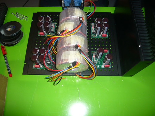
P1390019
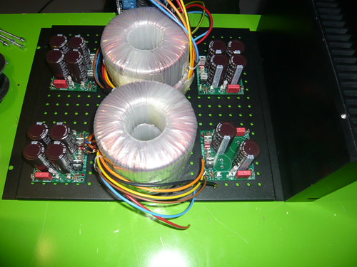
stacked
Hi Everybody,
getting closer and closer to the end of the amplifier build.
I have to fit 4 transformers into a given space and have two options only.
Either stack them or install them vertically.
Now I am aware that both solution are reputated to be, well let's say "suboptimal", but I am still unsure what evil to choose.
I would be glad if the more experienced amp-builders on here could give me some hints.
Kindly note that in any case the transformers will be shielded with vertical iron or stainless sheets on both sides.
I have attached two pics to illustrate what I mean.
Cheers,
Max
P1390019
stacked
- Status
- This old topic is closed. If you want to reopen this topic, contact a moderator using the "Report Post" button.
- Home
- Amplifiers
- Solid State
- SymAsym - "The Sequel", AAK's Rev_1.4 PCB Builders Thread