Hi folks.
I was wondering if anybody here has experience with DC servos for fully balanced stages, preferably discrete ones ? I've searched the net and this forum, but found nothing... or maybe I missed it...
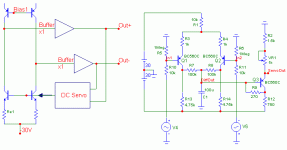
Basically, I want the servo to drive BJTs constant current sources of a balanced preamp stage (see attached schematic). The right voltage has to be a rough -21.75V, with a DC "gain" of -56dB (+/-160uV at servo output give +/-100mV offset at preamp outputs).
As I'm a little bit reluctant to use opamps, I started to think of something discrete, mainly teased by a Fred Dieckmann's post.
I started with a classical diff pair whose inputs are connected to the preamp's outputs. The pair's outs are summed through 2 resistors (R7 & R8) to keep only the difference signal (DiffOut). Here, the C1 cap provides low-pass filtering before entering a common collector stage, which shifts the output to the right level (-21.75V) via VR1. A local feedback resistor (R9) lowers the "gain" to -56dB.
Simulations of this design give the awaited behavior : right DC gain of -56dB, right value for the output voltage, right "slope" (100mV in -> 160uV out).
Thus I implemented this in the preamp design. Alas ! My simulator (Microcap 7) fails to reach the DC operating point
So I wonder if my servo design is right from the conceptual point of view, or if it is just a simulation problem. Am I doing something wrong ?
By the way, if anybody can provide me with links or references for such a design, it will be greatly appreciated Any hints ?
Thanks in advance.
I was wondering if anybody here has experience with DC servos for fully balanced stages, preferably discrete ones ? I've searched the net and this forum, but found nothing... or maybe I missed it...
Basically, I want the servo to drive BJTs constant current sources of a balanced preamp stage (see attached schematic). The right voltage has to be a rough -21.75V, with a DC "gain" of -56dB (+/-160uV at servo output give +/-100mV offset at preamp outputs).
As I'm a little bit reluctant to use opamps, I started to think of something discrete, mainly teased by a Fred Dieckmann's post.
I started with a classical diff pair whose inputs are connected to the preamp's outputs. The pair's outs are summed through 2 resistors (R7 & R8) to keep only the difference signal (DiffOut). Here, the C1 cap provides low-pass filtering before entering a common collector stage, which shifts the output to the right level (-21.75V) via VR1. A local feedback resistor (R9) lowers the "gain" to -56dB.
Simulations of this design give the awaited behavior : right DC gain of -56dB, right value for the output voltage, right "slope" (100mV in -> 160uV out).
Thus I implemented this in the preamp design. Alas ! My simulator (Microcap 7) fails to reach the DC operating point
So I wonder if my servo design is right from the conceptual point of view, or if it is just a simulation problem.
Am I doing something wrong ? By the way, if anybody can provide me with links or references for such a design, it will be greatly appreciated
Any hints ?Thanks in advance.
Attachments
Your circuit looks like a slow common-mode loop, which probably won't work in real life because of its enormously low gain. Why do you want 56dB of attenuation? Is the circuit supposed to be a common-mode loop, only setting common-mode levels while leaving differential signals and differential DC offsets alone, or do you want to make a DC feedback loop for reducing offsets?
Hi MarcelvdG,
The 56dB attenuation was given by the preamp sensivity to biasing : 160uV of variation in biasing the CCSs gives a 100mV absolute offset increase. So - in my mind - a 100mV variation at the inputs of the servo should lead to a 160uV variation at servo's output.
And yes, what I wanted was a DC feedback loop for reducing absolute offsets. But it seems that I took the wrong way... What would be a better solution ?
The 56dB attenuation was given by the preamp sensivity to biasing : 160uV of variation in biasing the CCSs gives a 100mV absolute offset increase. So - in my mind
- a 100mV variation at the inputs of the servo should lead to a 160uV variation at servo's output. And yes, what I wanted was a DC feedback loop for reducing absolute offsets. But it seems that I took the wrong way... What would be a better solution ?
here is my take on the bias source adjustment
http://headwize2.powerpill.org/projects/showproj.php?file=gilmore3_prj.htm
http://headwize2.powerpill.org/projects/showproj.php?file=gilmore3_prj.htm
Hi Kevin,
Thanks for the link ! And congrats for your projects. They look great ! I especially like your electrostatic headamp. Quite a nice design.
I already tried to model such a servo, even with a discrete one (ala N. Pass), but I was taking it the wrong way... Instead of driving the leds, I directly drived the base of the BJTs without any voltage reference. My mistake ...
I just wonder how to dimension the resistor at the output of the opamp... Is normally this output wandering near 0V, or something else ? if the opamp is saturated (output near Vsupply) I will have to face a dissipation issue... But that's nothing to deal with if it works the way I want.
Thanks again.
Thanks for the link ! And congrats for your projects. They look great ! I especially like your electrostatic headamp. Quite a nice design.
I already tried to model such a servo, even with a discrete one (ala N. Pass), but I was taking it the wrong way... Instead of driving the leds, I directly drived the base of the BJTs without any voltage reference. My mistake
... I just wonder how to dimension the resistor at the output of the opamp... Is normally this output wandering near 0V, or something else ? if the opamp is saturated (output near Vsupply) I will have to face a dissipation issue... But that's nothing to deal with if it works the way I want.
Thanks again.
Does 160uV of change of the base voltage of the current source transistors change the voltage at both outputs by 100mV (common mode), or does the difference change by 100mV (differential mode, offset)? Logically, a simulator should not show any offset at all if the circuit is completely balanced.
Does 160uV of change of the base voltage of the current source transistors change the voltage at both outputs by 100mV (common mode), or does the difference change by 100mV (differential mode, offset)? Logically, a simulator should not show any offset at all if the circuit is completely balanced.
Yes, it is common mode. Both outputs change exactly the same way (hopefully for a simulator...) Setting the CCSs bases at the right potential though a voltage source allows to have an offset within the tens of nV

Ha, simulations...
It sounds like you are trying to design a common-mode loop. In that case, you have to design an auxiliary circuit that takes the average of the output voltages, compares it to some reference value, amplifies the difference if necessary and puts that on the bases of the current source transistors. There is no need to keep the gain of this auxiliary circuit below -56dB; in fact, if you do keep it at or below -56dB, your common-mode output voltage becomes much too sensitive to the tolerances of the base-emitter voltages of the current source transistors. You have to make sure that the loop consisting of the main amplifier and auxiliary circuit is stable, for example by adding a big capacitor in the auxiliary circuit that rolls of its gain at high frequencies.
The simplest CM loop I can think of for your circuit consists of two equal resistors from the outputs to the bases of the current source transistors, one additional resistor from these bases to the negative supply rail and, if necessary, a frequency-compensation capacitor in parallel with this third resistor.
The simplest CM loop I can think of for your circuit consists of two equal resistors from the outputs to the bases of the current source transistors, one additional resistor from these bases to the negative supply rail and, if necessary, a frequency-compensation capacitor in parallel with this third resistor.
Hi back, Marcel.
Thanks a lot ! First simulations I quickly made showed that it works ! That's quite simple and straightforward. Reminds me of Ian's magical resistors in the Aleph X thread...
I may have a complicated mind, don't you think so ? Why make it simple if it can be more complicated ? I shoult have it in my signature
I will test it very soon, too nice to be true...
Thanks again.
Thanks a lot ! First simulations I quickly made showed that it works ! That's quite simple and straightforward. Reminds me of Ian's magical resistors in the Aleph X thread...
I may have a complicated mind, don't you think so ? Why make it simple if it can be more complicated ?
I shoult have it in my signature I will test it very soon, too nice to be true...
Thanks again.
- Status
- This old topic is closed. If you want to reopen this topic, contact a moderator using the "Report Post" button.
- Home
- Amplifiers
- Solid State
- Balanced DC servo for balanced stage ?