How works this circuit?
Because the schematic from the service manual about
DENON_PMA-1560_SM.pdf - Windows Live
is very hard to read for quickly understand, I have perform a redraw from the power amp section of one channel (see attachement)
Nevertheless I understand this circuit exactly.
What is the function of D503, D505, D507, D509, D511 and D513 (only 24,5uA flows across D507-513) ??
Parallel to R535 (2K7) is connected VR503 (adjust to 50K) and R533 (10K).
What effect has the controlling of the internal transistor from IC501 about the LED and TR603?
Thresholds-optobias about
http://www.diyaudio.com/forums/pass-labs/134502-thresholds-optobias.html?postid=1679112#post1679112
isn't similar. Also not the methodes listed here:
http://www.diyaudio.com/forums/pass...as-automatic-self-biased-overview-wanted.html
Attachments
I have discover some misprints partly from me and partly from Denon's service Manual (see upgraded attachement):
1) input differential stage (TR501, TR503, no twin/dual-jFET)
2) R623 (18k) in the pos rail for LED in IC501
3) D503/D505 are shottky diodes
1) input differential stage (TR501, TR503, no twin/dual-jFET)
2) R623 (18k) in the pos rail for LED in IC501
3) D503/D505 are shottky diodes
Attachments
Last edited:
At my opinion this is - in opposite to the output voltage dependend sliding bias about
Active bias circuit for operating push-pull amplifiers in class A mode
and to the driver stage current dependend sliding bias about
http://www.diyaudio.com/forums/pass-labs/134502-thresholds-optobias.html?postid=1679112#post1679112
an input voltage dependend sliding bias control about opto coupler. I don't still understand the theory of operation exactly, but it is clearly not an auto bias design respective a self biased design, because there are two bias potentiometers for adjusting;
1) one for the basic value (arround 20mA/each power bjt) and
2) one for the sliding bias threshold
Last edited:
no comments?
in the attachement additional high resolution schematics of preamp section so as the "Source Direct" control.
Very unusual for me is the use of electrolytic capacities in the baxandall equalizer section (tone control). What could therefore be the reason?
Foil caps like WIMA MKS in the aera between 0,1uF and 0,22uF are not sicnificant more expensiv than electrolytic caps
Attachments
Last edited:
Hi, the circuit works well, but you have a bug in your "Denon PMA-1560 Power amp redraw.ckt.pdf" file. Look at the service manual and the part D521(D531 in your pdf file).
Have you got a spice models of transistors in this circuit?
Can you post it here?
Have you got a spice models of transistors in this circuit?
Can you post it here?
Thank you very much for this advice to my drawing error - this diode (D521) must connect between the collectors of Tr507a/b and the basis Tr509 must directly connected to the collector of Tr507a.Hi, the circuit works well, but you have a bug in your "Denon PMA-1560 Power amp redraw.ckt.pdf" file. Look at the service manual and the part D521(D531 in your pdf file).
Have you got a spice models of transistors in this circuit?
Can you post it here?
I think, there are much more drawing errors - the genuine/original schematic in Denon's serv.man. has a very poor copy quality and is therefore very hard to read.
I haven't spice models of 2SK184, 2SK215 and 2SJ78 - otherwise I would have simulation results and would better understand the theory of operation concerning the dynamic bias control unit.
An "Off-Topic" question:
to find interesing vintage and currently available magazines arround electronic and audio I have start this thread:
http://www.diyaudio.com/forums/soli...rrently-available-electr-audio-magazines.html
perhaps you can check out such magazines from your country for posting about this mentioned thread - thanks in advance therefore.
Maybe in the follow forum there are informations concerning this:
http://www.bgaudioclub.org/forum/vi...&start=0&sid=8ca8d994da71bde2e7a1d177b04a654e
I wish you a good start in the new year.
Last edited:
Hi tiefbassuebertr,
Thanks you for your links. Yes, I know this Bulgarian forum.
About this denon circuit, if you want to simulate, you must have all transistor spice models or you should recalculate again. I tried to simulate this circuit, but with other part and the result is not very good.
I have Denon POA 6600 schema, this is the bigger model which also work in class A mode.
I have hybrid amp without feedback with tube preamp and power trasistor buffer in class AB mode. I want to change buffer with active bias circuit. Are you have some circuit about that?
I got hold of one of this amplifiers,but one of the inputfets are burnt,do I have to match them or can I just change one?
The first question is how do you know the input jfets are burnt?
But the direct answer is yes, the amp will perform best with jfets of equal gain and Idss.
Otoh, any approximately right pair of jfets put in the spot will cause the amp to make sound and function. Probably even one single jfet (if one is bad) will cause the amp to function.
IF that is all that is wrong.
It is somewhat unusual for just an input jfet to be bad, not unheard of, but somewhat unusual. So best to check the outputs too, unless you have no reason to believe that there is a problem there.
And, *both* channels fried??
_-_-bear
I just bought this amp from a fellow (havent gotten it yet).
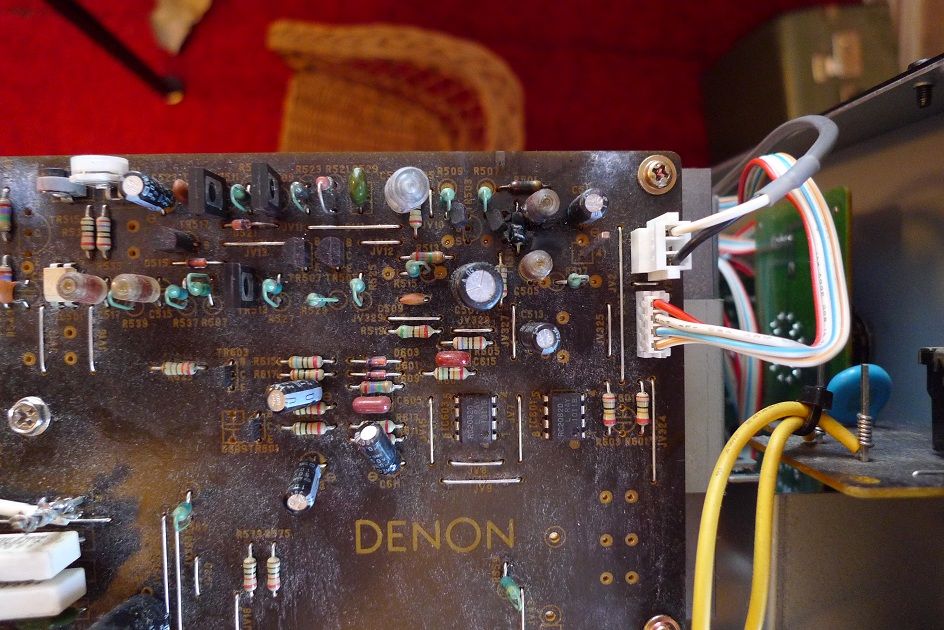
He tells me have changed the ouputtransistors and some smallsignal transistors,and got the amp working ,then suddenly the mess on the picture occcured.
It looks like the resistor ner the inputfet i burnt and possible the fet.
The input elyt looks like it blew to,don´t know what could have done this?
The other channe is working.
- Status
- Not open for further replies.
- Home
- Amplifiers
- Solid State
- Denon's MOS "Super optical Class A" from PMA1560 - how works this circuit