Hi!
Just connected and powered up my Crescendo Millenium amp (Elektor 2001).
According to the original article, the first thing to do, is to check the DC voltage on the output, and if this was higher than 0,1 v, then "something is wrong".
Well, I measured as much as -7v, so something was obviously wrong.
Quickly switched off and checked for any obvious visual, olfactory or thermal signs of catastrophic failure, but everything looked OK.
I then switched on power again, and the offset would drop to -1,2 v approximately after some 5-10 seconds, where it seemed to stop.
Switched off again, and re-checked for hot components.
Two 5w resistors on the protection card were warm, but in the article it said that "these resistors may become warm during certain failure modes and are therefore of 5W rating", so I assume that was "normal"
I then swapped in another amplifier card; Same result.
I then swapped in another protection/bias card; same result.
So unless something instantly fries on power-up, I assume that the problem is systematic rather than isolated to one mistake.
apart from that, I'm a bit clueless regarding what the problem could be..😕
Does anybody have some general advise based on my description of the problem?
Has anybody had similar issues with this amplifier in particular??
Any input would be greatly appreciated!
Best regards,
A good point Rikard!
I guess I assumed someone could have an answer based on past experience.
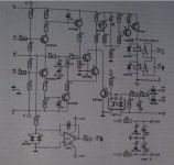
Anyway, found some images of the schematics for both the amplifier and the protection/ bias circuit!
Hopefully, someone better versed in Amplifier and Analogue circuitry than me can see what to look for..
I guess I assumed someone could have an answer based on past experience.
Anyway, found some images of the schematics for both the amplifier and the protection/ bias circuit!
Hopefully, someone better versed in Amplifier and Analogue circuitry than me can see what to look for..
Attachments
Perhaps your simply not allowing the amp to settle before measuring the DC offset ?
How is it after 1 minute ?
How is it after 1 minute ?
To determine the reason for the offset, you must investigate the voltage amplifier and the push pull buffer separately.
Probably an error in the voltage amplifier is the reason. For checking this stage allone, remove tthe MOSFET T12 and T13. Make a short connection between drain and source of T11 (T11 = Vbe multiplier).
Disconnect the right side of NFB resistor 12 K (R23? - hard to read exactly) and connect it with the short connection between drain and source of T11.
If the offset is still present, the output power stage isn't definitely the reason.
Now you can perform DC measurement both in pos. and neg. half and compare.
What type of ref LED is D1 and D2 (either 1V6/red or 2V1/yellow) ??
1V6/2,1-0V65 = 0V95 : 270R = 3,5/5,3 mA through diff amp (voltage across R8/9/13/14 each 1,75/2,65V)
Idle current through predriver (VAS):
3V9 - 0V65 = 3V25 : 33/39R = 98/83 mA
If I can see your results, I can say more.
You should check wether it s the amp itself or the DC servo that
are the source of the misbehaving.
First is to test the amp alone as follow :
-- remove R4 to disconnect the DC servo.
-- replace R2 by a 12K.
-- connect a 220uF cap in serial with R22.
Power on and measure the output dc voltage.
It should be at very low value, since the amp
has now a DC gain of 1 in respect to the input
offset.
If it works this way, then it s the DC servo that
is misbehaving.
If not, then perhaps the amp is oscillating,
in wich case it can be corrected by adding
a compensation that is ABSENT in the original
schematic...
Oh, relief!
I was starting to fear that I'd be stuck and clueless with my decade old obscure amplifier project, but advice and ideas suddenly rush in! 🙂
First of all, I'm not sure I'd like to keep the amp on for as long as one minute in case something overloads etc.. and even on the odd chance that it should eventually settle down to a normal offset voltage, the initial conditions tels me that there is something wring nevertheless.
I've used red LED's so that shouldn't be a problem. red in another thread about a guy that had used green ones, but it seems that only resulted in a slightly high bias current, not an offset problem like I have..
The approach of identifying if the problem is with the amp or the DC servo makes very good sense, and here i get a description on how to do it too, so I'll start there!
And thanks for all replies so far!!
Oh, one more thing..
Wahab, the bias servo return is connected to the card with a contact, is it sufficient to disconnect this, or should I still unsolder R4 for some other reason?
Wahab, the bias servo return is connected to the card with a contact, is it sufficient to disconnect this, or should I still unsolder R4 for some other reason?
Oh, one more thing..
Wahab, the bias servo return is connected to the card with a contact, is it sufficient to disconnect this, or should I still unsolder R4 for some other reason?
Right, so let R4 in place and just disconnect the contact...
And don t forget to ground the input before output DC measurements..
Wahab, thank you!!
I followed your instructions, and when I switched on the power, I measured 0,17 V!
Admittedly, not the "below 0,1v" quoted as normal in the magazine article, but I think this proves that the culprit is somewhere in the DC-servo circuit on the protection card....
Now I need to find out what I've done wrong with the protection card.. seems like I've made a systematic error as I had exactly the same result with both cards I tested..
The only deviation I know of, is that I used an OP177G opamp in stead of the originally specified OP77.
To the best of my understanding the OP177 should be a direct replacement for the OP77.. could this be where I went wrong??
Thanks for the schematics! Looks like a good sounding amp to me, I built a similar one myself with the 2SJ201/2SK1530 as output devices, and it sounds great!
I would also check that the LEDs have the same voltage across them. Any difference here is bound to cause different currents through the input stages with DC offset as the result. The DC servo is probably the problem here as it seems, but the amp should actually perform very good even without the servo if only the current sources in the input stage are matched properly.
🙂
/Rikard
Not the greatest of image quality on those schematics, but it turned out that my new PC doesn't wan't to talk to my old scanner, so I had to grab something off the web..
Good to hear you had success with these transistors in another build, perhaps I'll have some luck with my project too in the end!
I'll check the voltage across those LED's, doesn't cost me anything to do it anyway.
Even if I could make the amp run OK without the DC servo, that would feel a bit wasted since it is allready there, and it is supposed to work in the ffirst place, so I'd rather fix it than bypass it.
Just checked all the component placements and values, nothing obvious there either..😕
I followed your instructions, and when I switched on the power, I measured 0,17 V!
??
This is too high in respect of the expected value,
and at first look, the voltage divider that consist of
(R5+R4+R3+R2)/R2 has too high ratio, so the servo
has a limited range of correction that cant deal
with such an offset..
You can extend the DC servo correction range
by deacreasing R5 and R4 to 470K each.
In this case, C3 must be increased to 680nF.
Of course, reset R2 to 47K, i.e, its original value.
If you cannot find anything wrong with the LED voltages, then I would replace the transistors in the input stage, and perhaps the current sources. These are really cheap ones and any damage to them will cause problems.
🙂
🙂
Ouch..and I thought 0,17V was sort of ok... what range shold I have seen for the amplifier to be OK?
For the sake of thoroughness, R2 was not precicely 12 k. I soldered in a 15k resistor in parallel, and that gave me about 11,3k. Don't know if this deviation is significant, but I mention it just in case.
Hmmm.. if the range of the DC servo is innsufficient, the design was flawed from the start, or there is something wrong with my amp which the "normal" DC servo is not able to fully correct..
Looks like some more extensive fault finding will be called for here...
Is 0,17 volts without the servo? It isn´t too bad, so I would guess the remaining offset is down to different voltages across the LEDs, or slightly different values of the resistors around the current sources. Transistors seem ok then.
🙂
🙂
Is your amp not oscillating? This would show up as an offset on the output. Do you have a 'scope?
Fortunately, I have an Osciloscope, so I'll use that to check the output offset for any non DC output.
And I'll check the voltage across the LED's.
Regarding resistors, I took care to measure all resistors I used to make sure I only used those closest to nominal value and that the resistors installed on each card had a minimum relative tolerance spread.
The 0,17V was with the servo disconnected and the circuitry temporarily modified as per Wahab's instructions.
I allso did a quick check to see if the OP177 opamp in the DC servo circuit received correct voltage, and this was OK.
Last edited:
Some time ago I proposed a procedure for setting up a DC servoed amplifier.
First, with no servo attached the amplifier is set up to correct output and driver bias currents.
Second, the output offset is set when the amplifier is cold, say 1second after switch on.
Third, the DC servo is activated and the cold through warm to fully warmed up should stay at the cold output offset value.
Very few comments came back on this procedure, but one did agree that it made sense.
This procedure requires the amplifier to be initially set up without the DC servo working. Pull the IC out of it's socket.
BTW,
the opa177 is exceptional for a BJT input opamp for very good output offset and offset stability.
Normally FET input opamps are used for this duty, but the 177 spec looks perfect for servo duty.
Last edited:
Andrew,
Thanks for looking in to the OP177 issue. I did scrutinize the datasheets for both OP77 and OP177, and could my self find no cause for concern, but nevertheless, a second oppinion was much welcommed and I guess I can now close this one out as a root cause.
I am working from the assumption that the elektor design I have used is sound and should be working as intended without modifications as published, and that my problems are due to some mistake/ fault, not the basic design as such.
But having said that, the procedure you refer to would be interresting as a background for aiding investigation and fault finding.
Do you have a reference to this??
Br,
- Status
- Not open for further replies.
- Home
- Amplifiers
- Solid State
- Crescendo Millennium offset problem