I am hoping to get some advice on whether and how to repair my dead MF A1, or whether I should perhaps build another, more reliable, amp instead. If this in not an appropriate forum for such questions, I apologize in advance and ask if someone can refer me to a different forum.
Note that I have limited experience with electronics, so at this point I would only be considering replacing parts on the current amp or building from a kit, rather than building something from scratch.
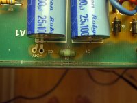
I have the original A1, the one with the two-part lid and the axial 10000uF caps. The caps do not have any apparent bulges in them.
Here is the problem with the amp. One day, it just failed to start up. So I replaced the slow-blow fuse in the back, thinking this would fix the problem. When I turned the amp back on (with the lid off), I noticed that after a few seconds some of the resistors (R1, R2, R30, & R31) started to glow and then smoke. Now they just smoke instantly when I power up the amp. Needless to say I cannot use the amp in this state.
What I am wondering specifically is whether the amp can be fixed by replacing all or some of the power supply parts (plus the R30 and R31 resistors), or whether I have to test each piece of the amp to determine if there are more extensive failures down the line. What is the best way to determine how to fix this? Or should I even bother? Thanks.
Note that I have limited experience with electronics, so at this point I would only be considering replacing parts on the current amp or building from a kit, rather than building something from scratch.
I have the original A1, the one with the two-part lid and the axial 10000uF caps. The caps do not have any apparent bulges in them.
Here is the problem with the amp. One day, it just failed to start up. So I replaced the slow-blow fuse in the back, thinking this would fix the problem. When I turned the amp back on (with the lid off), I noticed that after a few seconds some of the resistors (R1, R2, R30, & R31) started to glow and then smoke. Now they just smoke instantly when I power up the amp. Needless to say I cannot use the amp in this state.
What I am wondering specifically is whether the amp can be fixed by replacing all or some of the power supply parts (plus the R30 and R31 resistors), or whether I have to test each piece of the amp to determine if there are more extensive failures down the line. What is the best way to determine how to fix this? Or should I even bother? Thanks.
Attachments
I can guarantee that the output transistors have failed. These things run stupidly hot and this drastically shortens the life of all of the parts in there. R30 and R31 are emitter resistors for one channel, so those smoking means that the output transistors on that channel have failed.
Mark Hennessy has a great page about these amps here
I note that it looks like someone has already replaced the volume control - Mark goes into why those fail on his site (poor preamp design).
To bring the unit back to full working order, you will need to:
* Replace all the electrolytic capacitors, especially the 4 main power supply ones. These simply fail due to the high heat.
* Replace the output transistors. They may appear "custom" but they are really MJ2955/2N3055. I'd use the much more rugged MJ21193/4 series.
* Replace the fried resistors.
Edit: I just noticed you said that you started up the amp with the lid off - don't ever do this on an A1. The Lid is the heat sink for the amplifier, and without it, it will quickly fail. This is probably what has caused the damage you have now. The fuse likely failed simply due to age. You will need to clean off the original heatsink paste and replace it with fresh.
I would also replace the preamp as detailed by Mark.
Last edited:
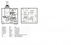
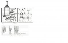
Schematics
The power supply schematic is sketched out on Mark Hennessy's page:
Mark's Project Pages - Image Viewer
Thanks for the tips jaycee. I will put together a parts list of what I would need and see what the total cost would be.
I just have two questions before I shop for parts. The first concerns the 10000uf capacitors. These are axial in my amp, and large axial caps are apparently uncommon. Can I use any axial capacitor as long as it is 10000uf, and rated at least for 25V and 85C? Or can I use the radial caps Mark recommends by extending the leads? I could not find any axial caps with the specs he recommends for radial caps so far.
The second question concerns the failed resistors. They are a dull green unlike the other resistors on board. What kind of resistors should I use here?
Thanks again.
Hello to all,
if i remenber correctly, on that PCB there are the footprints for radial caps in addition to the axials installed; if so i think you can use for example the Panasonic ECG 10000uF 35V 105°C. It's on Digi-Key, P/N: P6665-ND. The caps recommended by Mark seem out of stock.
if i remenber correctly, on that PCB there are the footprints for radial caps in addition to the axials installed; if so i think you can use for example the Panasonic ECG 10000uF 35V 105°C. It's on Digi-Key, P/N: P6665-ND. The caps recommended by Mark seem out of stock.
The green resistors are probably just some kind of high temperature resistor. They look too small. The original specifies 2W resistors - I'd probably try and squeeze some 3W wirewound (or metal oxide if I could) devices in there.
I'll also be very surprised if only the output transistors have failed. Expect to have to replace the driver transistors - BD135/136 labelled as TR6/TR8 on Mark's schematic. BD139/140 will be a suitable replacement here.
I'll also be very surprised if only the output transistors have failed. Expect to have to replace the driver transistors - BD135/136 labelled as TR6/TR8 on Mark's schematic. BD139/140 will be a suitable replacement here.
Musical Fidelity A1 restoration/upgrade
Hi all,
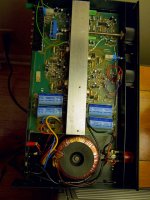
I’m restoring a Musical Fidelity A1 amplifier 20-years old. It is a MkII (pcb issue 8) in very good condition, fully functional and with no apparent damage from the heat except the bulging power capacitors. I need to change them, but after reading several websites (mostly the Mark Hennessy page) and threads here about the A1 and its relatives A100, MA50 or MA100, I’m also decided to make some improvements. These will be:
1) Direct connection from the RCA inputs to the power amp section through a 10 or 20k pot. I don’t need the phono or line preamp as I listen only to CD or audio files from my PC. Is it possible to completely disable all the pre-amp circuit and even desolder the unused parts from the pcb (I probably need to do this to make room for a delay/DC-offset protection module) without affect the power amplifier section?
2) I’m not going to re-use the original, beautiful but small, A1 box. I’ll install the pcb vertically in a new and better ventilated tower-like case (32x25x10cm) with a much bigger heatsink attached to the original U-shaped aluminium piece where the output transistors are. In the place of the original finned “lid-heatsink”, I’ll use the Aavid EK/B/300 heatsink (30x30x4cm), rated at 0.30ºC/W, with its fins vertically oriented for better dissipation, so I hope there will be no heat-related problems in the restored unit.
3) I’ll use a new fully-encapsulated power transformer, mounted on the rear plate of the box (but outside). It's a 2x18Vac dual secondaries type, wired to obtain the required 18v-0v-18v by joining the two 0v output cables in one. Here I have a doubt regarding its VA size. The 120VA Nuvotem 0120P1-2-018K is a perfect fit (104 mm diameter) and the 160VA is too wide for the new box. The original A1 transformer is around 100VA, so I think the 120VA will suffice. I will use the amplifier with a pair of small loudspeakers (nominal 4 ohms impedance) and I listen usually at low volume, so the limited A1 power is no problem. Do you think is there any advantage in going to the 160VA transformer? Perhaps its higher rating will stress too much the PSU caps and diodes.
4) I’ll use new Panasonic FC 105ºC-rated for all the electrolytic capacitors. The new four big PSU capacitors will be Evox-Rifa PEH536 10000uF/35V (same value but not rated at only 25V). They are 30x40mm (same diameter and a little taller than the originals), but with much better specs (ripple 4600mA, ESR 0.022Ω, 105ºC rated, 6000h life), and I’ll probably bypass them under the pcb with film types.
5) New diodes (at least the D1-D4 BY255 in the PSU), new small transistors (BC550C/560C and BD139-16/140-16) and, more important, new Onsemi MJ15003G/15004G TO-3 output transistors. From what I have read these are better sounding and more rugged that the originals 2N3055/MJ2955.
6) I’ll use new better power resistors (those on the pcb rated from 1 to 5W, like R1-2, R13-16, R30-31 and R39). I’m not sure about changing the other, smaller, metal film resistors (they look fine). My plan is to maintain all the original values, although I’ve read that it is possible to modify several of them if it is needed for decreasing a little the quiescent current, like R6/R11 or the output resistors R30/R31.
7) And, lastly, I’ll probably fit at the A1 output some on/off-thump and DC-offset protection for the loudspeakers, like the Velleman K4700 kit, the Dada protection-delay circuit, or other similar. If I’m not wrong, the “thump” at turn-on/off is avoided by disconnecting during about 5 seconds the amplifier from the loudspeakers, but in the A1 user’s manual there is a warning specifically against this: “You MUST connect the A1 to a pair of loudspeakers before you switch it on. If this is not done, it is relatively easy to damage the output stage”. Does this mean that these output protection circuits are not recommended? If the temporally disconnected A1 output is directed to a power resistor (like 8ohms/50W) instead of the loudspeaker binding posts this problem is solved?
Do you have any recommendations? Is there any mistake in the plan I’ve outlined? Please, I’d like to know your comments before start to buying the parts. Thanks in advance for your help
Best regards
Jose
Hi all,
I’m restoring a Musical Fidelity A1 amplifier 20-years old. It is a MkII (pcb issue 8) in very good condition, fully functional and with no apparent damage from the heat except the bulging power capacitors. I need to change them, but after reading several websites (mostly the Mark Hennessy page) and threads here about the A1 and its relatives A100, MA50 or MA100, I’m also decided to make some improvements. These will be:
1) Direct connection from the RCA inputs to the power amp section through a 10 or 20k pot. I don’t need the phono or line preamp as I listen only to CD or audio files from my PC. Is it possible to completely disable all the pre-amp circuit and even desolder the unused parts from the pcb (I probably need to do this to make room for a delay/DC-offset protection module) without affect the power amplifier section?
2) I’m not going to re-use the original, beautiful but small, A1 box. I’ll install the pcb vertically in a new and better ventilated tower-like case (32x25x10cm) with a much bigger heatsink attached to the original U-shaped aluminium piece where the output transistors are. In the place of the original finned “lid-heatsink”, I’ll use the Aavid EK/B/300 heatsink (30x30x4cm), rated at 0.30ºC/W, with its fins vertically oriented for better dissipation, so I hope there will be no heat-related problems in the restored unit.
3) I’ll use a new fully-encapsulated power transformer, mounted on the rear plate of the box (but outside). It's a 2x18Vac dual secondaries type, wired to obtain the required 18v-0v-18v by joining the two 0v output cables in one. Here I have a doubt regarding its VA size. The 120VA Nuvotem 0120P1-2-018K is a perfect fit (104 mm diameter) and the 160VA is too wide for the new box. The original A1 transformer is around 100VA, so I think the 120VA will suffice. I will use the amplifier with a pair of small loudspeakers (nominal 4 ohms impedance) and I listen usually at low volume, so the limited A1 power is no problem. Do you think is there any advantage in going to the 160VA transformer? Perhaps its higher rating will stress too much the PSU caps and diodes.
4) I’ll use new Panasonic FC 105ºC-rated for all the electrolytic capacitors. The new four big PSU capacitors will be Evox-Rifa PEH536 10000uF/35V (same value but not rated at only 25V). They are 30x40mm (same diameter and a little taller than the originals), but with much better specs (ripple 4600mA, ESR 0.022Ω, 105ºC rated, 6000h life), and I’ll probably bypass them under the pcb with film types.
5) New diodes (at least the D1-D4 BY255 in the PSU), new small transistors (BC550C/560C and BD139-16/140-16) and, more important, new Onsemi MJ15003G/15004G TO-3 output transistors. From what I have read these are better sounding and more rugged that the originals 2N3055/MJ2955.
6) I’ll use new better power resistors (those on the pcb rated from 1 to 5W, like R1-2, R13-16, R30-31 and R39). I’m not sure about changing the other, smaller, metal film resistors (they look fine). My plan is to maintain all the original values, although I’ve read that it is possible to modify several of them if it is needed for decreasing a little the quiescent current, like R6/R11 or the output resistors R30/R31.
7) And, lastly, I’ll probably fit at the A1 output some on/off-thump and DC-offset protection for the loudspeakers, like the Velleman K4700 kit, the Dada protection-delay circuit, or other similar. If I’m not wrong, the “thump” at turn-on/off is avoided by disconnecting during about 5 seconds the amplifier from the loudspeakers, but in the A1 user’s manual there is a warning specifically against this: “You MUST connect the A1 to a pair of loudspeakers before you switch it on. If this is not done, it is relatively easy to damage the output stage”. Does this mean that these output protection circuits are not recommended? If the temporally disconnected A1 output is directed to a power resistor (like 8ohms/50W) instead of the loudspeaker binding posts this problem is solved?
Do you have any recommendations? Is there any mistake in the plan I’ve outlined? Please, I’d like to know your comments before start to buying the parts. Thanks in advance for your help
Best regards
Jose
Thank you for your answer, Zen.
I've read about the Pass F5 in Diyaudio and it's very interesting. If some day I build a power amplifier for my main system, I'll probably use it. Anyway, I'd like to upgrade my MF A1, now it's opened. I use it as second audio system in another small room and I like very much its sound. I don't think it would be too much work (it's just swapping of several parts and audio is a hobby, isn't it?) and, regarding cost, the only really expensive part is the huge heatsink, but using it will kill any A1 reliability trouble from the beginning. My plan could be also simplified if necessary.
Please, have you (or somebody else) any specific comments to the upgrades 1 to 7 I've outlined in my previous post? I'd like read your knowledgeable opinions before ordering the components
Thanks in advance
BTW, your avatar brings back childhood memories to me... Pippi Langstrumpf ("Pippi Calzaslargas" here in Spain) and its monkey, "Mr. Nilsson"
Great! I’m looking forward to see your tutorial on the A1 soon, Zen Mod.
Please, I’d be very grateful if you could give advice regarding the new power transformer on my A1 because I’m still in doubt about its VA size.
I’ll probably buy the Nuvotem 0120P1-2-018K which is a 120VA unit with one 230Vac primary and two 18Vac secondaries. If I’m not wrong, to obtain the required 18v-0v-18v ac supply I have to join the two 0v output cables (black and orange) and solder both to the “0V” input on the A1 pcb. The other two wires (red and yellow) are soldered each to one of the two “~” inputs on the pcb. Just to be sure, this is the correct wiring, isn’t it?
I have a doubt regarding the size. The original A1 transformer is around 100VA, so I think the 120VA will suffice and its 104mm diameter is perfect for the box I have. I will use the amplifier with a pair of small 4 ohms loudspeakers in a smallish room and I listen usually nearfield at low volume, so the limited 20W power is not a problem, but I’ve read that the A1 is not at ease with a 4 ohms load. Perhaps in this case a bigger transformer is better, helped by the beefier MJ15003/4 output transistors and a big 0.30ºC/W heatsink to cool all down. Will its higher rating and inrush current stress too much the PSU caps and diodes?
What do you think about it? Is there any advantage in going from a 120VA to a 160VA transformer?
Thanks again in advance
Best regards
Jose
Attachments
considering that stock A1 ( if you're lucky not to have one with crippled bias ) is cruising somewhere at 700mA/2 x 22V per channel - that's 30W ; say that rest of circ is drawing some 10W max , so you have around 40W of draw per channel
80W for both - my logic is to use at least 200VA xformer if shared between channels
if you are going for one xformer per channel , 120VA is more than fine
to further refine things - look at ,say, F5 manual ( FIRST WATT HOME) and observe how NP use two bridges (one per winding) ..... old trick , also used by Naim boyz
that way you'll have cleaner audio gnd , less spikes and buzz in xformer
for going completely nutz - use discrete bridges , made with either shottky or fast T0220 cased diodes
The original transformer is only 100VA iirc. You would join the black and yellow wires together and connect this to the 0V point.
I wouldn't bother "going nuts" on this amplifier at all. What I would do is replace all of the capacitors, and replace the output transistors (which are MJ2955/2N3055s) with more rugged MJ15024/5 or MJ21193/4 devices. Also as Mark says, build a replacement preamp and bypass the dreadful one in the amp itself.
I wouldn't bother "going nuts" on this amplifier at all. What I would do is replace all of the capacitors, and replace the output transistors (which are MJ2955/2N3055s) with more rugged MJ15024/5 or MJ21193/4 devices. Also as Mark says, build a replacement preamp and bypass the dreadful one in the amp itself.
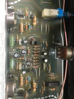
Hi - all slightly off the original topic (as my A1 is working, currently at least) and have some queries from others who have worked on this amp. I have the original A1, with two-piece top heatsink, bad (pre Alps) volume control, and the radial power supply caps.
Questions:
Im trying to figure out if the Philips blue metallic-shell electro caps in the phono section are factory standard? I cant see any temperature rating on them. I do intend doing a full recap.
What is a modern replacement for the BC547 and BC557? I have a slight channel imbalance and I intend shotgunning all small transistors as I suspect these will be well-cooked with years of high temperature running.
Some other observations:
Mark Hennessey's page recommends replacing the outputs with modern MJ's for increased reliability, which I will also do.
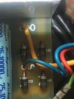
Power supply diodes have been running hot, they are only 1N5402, I intend uprating these to say 1N5406/1N5408, and also lifting the replacements off the board by a few mm,
Mark Hennessy's page also includes a DIY pre-amp upgrade to replace the somewhat noisy (running at the gain it is set at) TL084, which I also intend building.
Any thoughts from anyone who has embarked on the above, or can assist with the above?
Questions:
Im trying to figure out if the Philips blue metallic-shell electro caps in the phono section are factory standard? I cant see any temperature rating on them. I do intend doing a full recap.
What is a modern replacement for the BC547 and BC557? I have a slight channel imbalance and I intend shotgunning all small transistors as I suspect these will be well-cooked with years of high temperature running.
Some other observations:
Mark Hennessey's page recommends replacing the outputs with modern MJ's for increased reliability, which I will also do.
Power supply diodes have been running hot, they are only 1N5402, I intend uprating these to say 1N5406/1N5408, and also lifting the replacements off the board by a few mm,
Mark Hennessy's page also includes a DIY pre-amp upgrade to replace the somewhat noisy (running at the gain it is set at) TL084, which I also intend building.
Any thoughts from anyone who has embarked on the above, or can assist with the above?
Attachments
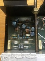
OK. Did a full recap and uprated the PS diodes.
This thing sounds fine to me. You'd have to convince me to upgrade the preamp section. I dont have any noise on the volume pot. Seems like a lotta work for what kind of benefit exactly?
I have removed the side panels and convection is helping the cooling. It sounds pretty great. And nice and quiet in between playing music too
Nice - that looks like a simpler solution to what Mark Hennessey proposes (as great as his work looks).I've replaced TL074 in my A200 with OPA1679.
Nice improvement.
Is the OPA1679 a straight-up drop in replacement? No additional ceramics required to stop any oscillation with the new chip?
Thanks!
- Home
- Amplifiers
- Solid State
- Musical Fidelity A1 Integrated repair/upgrages