see an inconsistent in what You are writing?
In a post earlier here You tell me that Goldmund on purpose construct the PSU to "kneal down" when high loads are present. In Your example over here You add another 10% to the rail voltage when calculating the power loss.
In many/most countries, Mains voltage is Vnominal +/-10%
The 80Vdc +10% is the actual peak Rail voltage, Loaded.
Unloaded, it would be even higher, due to the regulation of the transformer used. (in case of a 625VA, by +4%, so would make 92.5Vdc)
As mentioned at the bottom of my post : Die temperature would be some 15% above it's Absolute maximum rating for the max dissipation level of an 8 Ohm load.
The only way to prevent that is to make sure that Rail voltage goes down sufficiently under load. (sqrt 1.15 = 1.072+something)
How ? By Not making the power supply a Stiffy !
(250W/8 continuous is 63Vp + something as a quarter volt)
How to accomplish that, with 2 large transformers in a monaural power amp ?
Answer : By having small size smoothing caps, instead of a closet full.
(the use of a low uF count also serves another purpose, a primary one)
Why did Goldmund use only 3 pairs of Lateral Mosfets ?
Because they chose to.
Why did Goldmund use a moderate size heatsink ? (with room for a much larger one)
Because they chose so.
Deliberate Choices, not Flaws.
Goldmund had totally other priorities than Krell, so what they made is Not a Krell, but quite the opposite.
Last edited:
the calculations above
Oiphy,
glad to be of some use.
(passing on some understanding, or a way of looking at things, is the reward for writing a post. Not winning contests, gave that up decades ago)
The "calculations" are just global, not entirely accurate, merely aimed at giving a description of the issue at hand.
Physical limits can not be surpassed, in this case a thermal one, unless there's something as Negative thermal resistance (which there is not)
Thank you nikosokey for your kind words. And thank you jacco vermeulen for your clarifications.
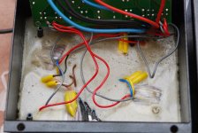
Here are two pictures from whats inside one of the the MM29 transformer boxes. Perhaps the MM9.2 uses a similar solution with a PCB inside? However there are four smaller toroidal transformers in this box.
Here are two pictures from whats inside one of the the MM29 transformer boxes. Perhaps the MM9.2 uses a similar solution with a PCB inside? However there are four smaller toroidal transformers in this box.
Attachments
"The "calculations" are just global, not entirely accurate, merely aimed at giving a description of the issue at hand." that would be the learning part
Goody
")
That's the response that puts a content smile on my face.
(mr. thank you, for naming the right number, really doesn't
 )
)Discrete audio amp design is a dying hobby/skill/art/science, stimulating others is a way of preventing to become an eccentric with an extinct hobby. (much nicer to be an eccentric with a widespread hobby)
In many/most countries, Mains voltage is Vnominal +/-10%
The 80Vdc +10% is the actual peak Rail voltage, Loaded.
Unloaded, it would be even higher, due to the regulation of the transformer used. (in case of a 625VA, by +4%, so would make 92.5Vdc)
As mentioned at the bottom of my post : Die temperature would be some 15% above it's Absolute maximum rating for the max dissipation level of an 8 Ohm load.
The only way to prevent that is to make sure that Rail voltage goes down sufficiently under load. (sqrt 1.15 = 1.072+something)
How ? By Not making the power supply a Stiffy !
(250W/8 continuous is 63Vp + something as a quarter volt)
How to accomplish that, with 2 large transformers in a monaural power amp ?
Answer : By having small size smoothing caps, instead of a closet full.
(the use of a low uF count also serves another purpose, a primary one)
Why did Goldmund use only 3 pairs of Lateral Mosfets ?
Because they chose to.
Why did Goldmund use a moderate size heatsink ? (with room for a much larger one)
Because they chose so.
Deliberate Choices, not Flaws.
Goldmund had totally other priorities than Krell, so what they made is Not a Krell, but quite the opposite.
Well, You avoided the core question here.
If the power supply kneals down inder full load (250W in 8 Ohms = 44,72V or 63,24V peak value) Why calculate Your loss as if the PSU is stiff?
I would have answered: To make a SOA as per dissipation.
And the chouses Goldmund made is possibly due to calculations they have made based on their philosophy in making amplifiers.
I only seeked what they might had in mind when doing so.
Deliberate or not.
The +/- 10% variation is a guarantee the most countries powersuppliers give. They operate with quite another tolerances in real life.
Here in Norway the voltage is not allowed to go more than 8% over nominal value, or 6,5% under nominal value. This is not ment to counteract Your definition of +/-10%, but just as an additional fact.
A powersupply capable of delivering 10Amps into 4 Ohm, would I not speak of a knealing one when talking about a moderate 5,5Amps in 8 Ohms.
I am sorry, but thats a pretty stiff powersupply as per my terms.
Still a weak one when KRELL comes in to the discussion, but still?
The choise of capacitor bank is one of wich capabilities one would like to get from the finished amplifier. I am quite confident in what I am doing to this amp, but have no intentions to introduce it to the masses as a commercial product. The amp is to please me and my preferanses regarding to music reproduction. Also the engineers at Goldmund would have agreed to the fact that it is really what matters afterall.
Shouldn't each one of us think like that, there would only be one anplifier alone to serve the public. Because some engineers agreed that this is it.
The perfect amp is born and will never be superceeded.
Will my alterations around the power supply give me an amplifier superior to all others? No, I don't think so. But I probably will get something in between of what the engineers at Goldmund and what I have as a preferance in an amplifier. For some reason I think both I and the guys at Goldmund will like the result. For me is the only objective to make en amplifier I like.
But still, we seems to have similar calculators.
We only seems to use the results in a slightly different way.
I still are looking forward to listen to the result. For as I said, I am very confident I get an amplifier wich sounds as good as it can, and will please me perhaps for years to come.
Will post some pictures when there is anything to present here.
Have a Nice evening all.
Thank you nikosokey for your kind words. And thank you jacco vermeulen for your clarifications.
Here are two pictures from whats inside one of the the MM29 transformer boxes. Perhaps the MM9.2 uses a similar solution with a PCB inside? However there are four smaller toroidal transformers in this box.
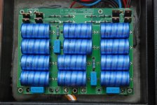
In addition there is four capacitors on each PCB too?
What are the value on them?
Something tells me this is a quite capable one.
Wonder if this peak sving of 28Amps is continious or not?
POWER
- Nominal power : 2 x 250 W RMS (2 - 8 Ohms).
2 x 150 W RMS (1 - 16 Ohms).
- Maximum instantaneous power : 2 x 500 W RMS (8 Ohms).
- Maximum voltage swing : 80 V peak.
- Maximum current swing : 28 A peak.
These figures for both channels driven.
The smaller transformers is probebly to power the security and softstart cirquits, and probably for the input and driverstages of the amp?
Just guessing. I have none of theese so far.
Member
Joined 2009
Paid Member
Another way of reducing the rail voltage is to use an inductor after the rectifier. The value of the inductor will determine the final voltage and it must be rated for the current it has to handle or it will spew magnetic flux into the amplifier. But it will smooth the rectifier pulses somewhat giving you a cleaner supply and it will allow you to use larger capacitors afterwards to control ripple voltage.
In addition there is four capacitors on each PCB too? Yes
What are the value on them? 1000uF each.
Wonder if this peak swing of 28Amps is continuous or not ?
- Maximum current swing : 28 A peak.
The datasheets of the 125W devices both state that Max drain current (Id) is 8A.
3 Lateral Mosfets in parallel : 3 x 8 = 24A
That is maximum continuous output current.
Please don't believe me, and read what the Id/Vds graph says above the 8A line after the word : Idmax.
That makes the 28A ?
(for those interested :
Max continuous current of a Lateral Mosfet is due to the formation of so-called hot-spots.
Basically, when the channel of a Lateral heats up, the hot-spots raise the channel resistance, by which the current is limited.
Pretty much the same principle by which Lateral Mosfets self-protect : during a short, the channel turns high-Ohmic, cool it down and the channel opens up again. Think thermo-static valve.
Current peaks do not last long enough to heat up the die, so peak drain current can be much higher than the 8A continuous for the 125W, or the 7A for the 100W devices.
Monaural power amps I built with 4-pair J50/K135 output stages easily managed a multitude of the 7A per device during short peak bursts. Something the datasheet doesn't tell you, btw.)
Last edited:
The datasheets of the 125W devices both state that Max drain current (Id) is 8A.
3 Lateral Mosfets in parallel : 3 x 8 = 24A
That is maximum continuous output current.
Please don't believe me, and read what the Id/Vds graph says above the 8A line after the word : Idmax.
That makes the 28A ?
(for those interested :
Max continuous current of a Lateral Mosfet is due to the formation of so-called hot-spots.
Basically, when the channel of a Lateral heats up, the hot-spots raise the channel resistance, by which the current is limited.
Pretty much the same principle by which Lateral Mosfets self-protect : during a short, the channel turns high-Ohmic, cool it down and the channel opens up again. Think thermo-static valve.
Current peaks do not last long enough to heat up the die, so peak drain current can be much higher than the 8A continuous for the 125W, or the 7A for the 100W devices.
Monaural power amps I built with 4-pair J50/K135 output stages easily managed a multitude of the 7A per device during short peak bursts. Something the datasheet doesn't tell you, btw.)
I actually quoted the GOLDMUND own datasheet for the amplifier.
Go figure what THEY tell us. FYI: http://www.google.no/url?sa=t&rct=j...UPnY9OY1e2DPhHT9H1O3GiA&bvm=bv.42452523,d.bGE
Tell me, WHAT is Your issue? No confidence at all?
12
SPEED
- Slew rate : > 200 V/us
- Rise time : < 300 ns.
CROSSTALK
- Separation : > 100 dB between channels. Isolated ground.
NOISE
- Signal-to noise ratio : > 115 dB (0.01 Hz - 1 Mhz).
- Weighted ASA A : > 130 dB.
OPERATING TEMPERATURE
- Room temperature : -30 to +40 degrees Celsius
(-22 to +104 degrees Fahrenheit).
- Internal temperature : +45 to +65 degrees Celsius
(+113 to +149 degrees Fahrenheit).
POWER SUPPLY
- Nominal line voltage : 117, 234 V (switchable).
- Input voltage range : +/- 10 %.
- Maximum power consumption : 2000 W.
- Power used in standby : 120 W.
- 8 toroidal transformers, 8 separated power supply.
GROUNDING
- Separated ground for each channel.
- Floating chassis connected to mains earth.
- Switch for optionally connecting both.
SAFETY FEATURES
- AC voltage fuse : min 10 A slow-blow for 220 V / 16 A slow-blow for 110 V.
User Manual – Goldmund Mimesis 22M Power Amplifier 12
(Page 14 of the PDF-document equals GOLDMUndS Page 12 in the user manual.)
There's not much sense in comparing the MM9/9.2 with the MM29.
(and I have no idea what's inside the Mimesis 29M )
The Mimesis 29 uses TO3P devices in the output stage, 6 pairs of J162/K1058.
(Mimesis 28 has 4 pairs per channel of those)
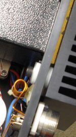
For those who missed the very unusual way the heatsink is attached to the case of the Mimesis power amp (MM29 in this example)=>
(and I have no idea what's inside the Mimesis 29M )
The Mimesis 29 uses TO3P devices in the output stage, 6 pairs of J162/K1058.
(Mimesis 28 has 4 pairs per channel of those)
For those who missed the very unusual way the heatsink is attached to the case of the Mimesis power amp (MM29 in this example)=>
Attachments
Last edited:
Hitachi s laterals are extremely rugged components that could
stand extreme abuses that would be lethal for BJTs with supposedely
higher power ratings.
I used 3 pairs of TO3 devices with a 2X48V AC transformer , wich put
the power output to about 125W/8R with a stereo build , yet even
using a 4R load at full volume for hours in an overheated stage and
without any active cooling didnt seems to bother thoses devices
during the 20 years or so of such harsh condition , the amp is still
working and kicking.
From this extensive real world and long term testing i came to the conclusion
that those devices can handle a power output that is 70% of their TDP ratings,
that is , a pair of 100W TDP devices is enough for 70W RMS output , so using
three 125W TO3 pairs should be adequate for up to 260W RMS , short of the
Tanbergeren targeted 350W wich would require four pairs if reliability is a concern.
As for the Goldmund itself , well , i explained in another thread that it s really
not my cup of tea given that i found through simulations that excepted slew rate
it is a relatively low performing amp , good enough for vinyl , tuner or K7 sources
but well below the CD format quality requirements.
As for the Goldmund itself , well , i explained in another thread that it s really
not my cup of tea given that i found through simulations that excepted slew rate
it is a relatively low performing amp , good enough for vinyl , tuner or K7 sources
but well below the CD format quality requirements.
Hello Wahab,you can say from simulations if an amp performs low in therms of sound ?
Can the simulations assure us that an amp has great sound ?
As I understand the thd&imd for goldmund are decent to good ~0.01 .
But may be the thd are not a factor important to say that an amp has good sound .
So what parameters do you simulate ?
- Home
- Amplifiers
- Solid State
- The Very Best Amplifier I Have Ever Heard!!!!