I would be nice to know the bandwidth/resonant freq. of that L/R combo to see what it should be....
According to this... CalcTool: RLC or LC circuit calculator
the .22R/2uH has a limited bandwidth (17Khz). I use 10R/1.5-2UH in my amps (better BW - 800k) since the only purpose is to attenuate RF at the OP. (absorbed by speaker wire , etc)
So , by all reasoning ... .22R/2uH IS WRONG.
EDIT: unless ,in the case of the goldmund , the limited BW is there to accommodate RF created from WITHIN the amp.
OS
that was a serious point i think ....worth looking at
as about the blody resitors is for sure 0.22 R i can measure it for you and post a picture
snsg001
The blue caps are styroflex HF blockers, and the green res. are tubed metalloxide Withrom induct. free HiWatt 5% resistors.
CB
Thanks all for the replies to my question.
Yesterday I received the PCB from Bigpanda (the budget version with the white silkscreen).
I am preparing the parts order and I will order Carbon Composite resister for the gatestopper & R23; Metal-oxide resistor for the Zobel & other high power resistors.
For R36, I will order both 0.22R & 22R, I can either use Carbon Film or Metal-oxide.
For the 10nF bypass capacitors, I can try some NPO ceramic & polyester cap in my parts bin.
Cheers, Stanley
For
the R of the R//L of the Thiele Network is likely to be from 1r0 to 10r.For R36, I will order both 0.22R & 22R,
Yes it could be outside that range but would be very unusual.
Buying the two extremes of 0r22 and 22r will leave you with no workable solutions.
Hotzman
Have you recieved your transformer??? I am curious to hear results from other builders.
By the way, have you notice what Alex wrote about T4 in # 1252. I have looked at your pictures. It was difficult to clearly see if you have connected T4 to ground plane.
To day I recieved the "white silkscreen PCB" from Bigpanda. At the time I am
working on a "rev. 2" of the clone.
The plan is to:
1. Move all components to the front end and the output FETs from my "old" PCB to the new PCB.
Since I was (among) the first one(??) to built, serveral changes was done. Components in and out. Desoldering and soldering results in lots of fluxs on the board.
2. Use the separate power to the front ends as it is now.
3. Separate the protection part of the PCB (cut it) and move it close to the output terminals.
4. Add another two capasitors for the output close to the power bridges and go to -VVC and +VVC.
The purpose is, among other things, to avoid any AC to reach the main PCB.
So far this is only thougts, but if I remember correct this some of the criticism
on the Goldmund clone in the early posts in this thread, and that this is one way to meet this criticism.
I will also take my time to see what comes out of the discussion in the latest posts about R36 (size and type ), C20-26 and how to connect them(from drain to common earth or to the heatsinks).
Comments are very welcome.
Eivind Stillingen
Regarding R36 and the Thiele network.
As I see this you have two option here. 1. Stay with the original design.
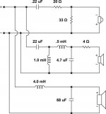
2. Modify it so it will work with your speaker cable and speaker crossover filter. I have seen crossover filters that have 68uF across the woofer.
I do not think that the GM will work with such crossover filter.
If you go for nr. 2 you need to read this:
The inductor is pretty standard fare at the output of amplifiers. Its usually a very small value (2-6uH is typical) and its function is to prevent the amplifier breaking into RF oscillation due to stray capacitance on the output (due to cables, and the speaker/the speaker crossover). Simply put, at very high frequencies (well above audio) the inductor presents a small impedance which stops the amp seeing a 'pure' capacitative load.
Connecting a resistor in parallel with this inductor then damps the tendency of the inductor to ring with this stray capacitance on the output, so as to make things behave better.
You can test the amp with a scope over its full power and input signal range into the precise load it's driving to make shure it behaves stable.
As I see this you have two option here. 1. Stay with the original design.
2. Modify it so it will work with your speaker cable and speaker crossover filter. I have seen crossover filters that have 68uF across the woofer.
I do not think that the GM will work with such crossover filter.
If you go for nr. 2 you need to read this:
The inductor is pretty standard fare at the output of amplifiers. Its usually a very small value (2-6uH is typical) and its function is to prevent the amplifier breaking into RF oscillation due to stray capacitance on the output (due to cables, and the speaker/the speaker crossover). Simply put, at very high frequencies (well above audio) the inductor presents a small impedance which stops the amp seeing a 'pure' capacitative load.
Connecting a resistor in parallel with this inductor then damps the tendency of the inductor to ring with this stray capacitance on the output, so as to make things behave better.
You can test the amp with a scope over its full power and input signal range into the precise load it's driving to make shure it behaves stable.
Attachments
the R of the R//L of the Thiele Network is likely to be from 1r0 to 10r.
Yes it could be outside that range but would be very unusual.
Buying the two extremes of 0r22 and 22r will leave you with no workable solutions.
Hi Andrew,
I agreed that 22R is a bit too high for this application.
I have build Dr. Bora's Sigma which use a similar L-FET topology, I used 2R7. I also build a LMe49830 with L-FETs, again I used the same value for the Thiele Network.
I agreed with Tommy, it may be a matter of trial & error to match the speaker.
Cheers, Stanley
100VdcI have 10000uf/100V capacitor, what is the maximum voltage for this cap?
Some information about BUZ900 / 905 here :
http://www.diyaudio.com/forums/group-buys/175296-pcb-order-goldmun-clone-33.html#post2493765
http://www.diyaudio.com/forums/group-buys/175296-pcb-order-goldmun-clone-33.html#post2493765
Magnatec BUZ901/BUZ906 Maximum Drain Source Voltage 200V
Are the 200v Magnatec better than the 160v or make that no difference??
I think it's only depend on the transformer you use.
Rudy
Are the 200v Magnatec better than the 160v or make that no difference??
I think it's only depend on the transformer you use.
Rudy
Here's a complete list of all the MOSFETS and equivalents that can work in this amplifier:
Plastic Case:
Hitachi 2SK1058/2SJ162 (Obsolete)
Renesas 2SK1058/2SJ162
Hitachi 2SK1057/2SJ161 (Obsolete)
Renesas 2SK1057/2SJ161
Hitachi 2SK1056/2SJ160 (Obsolete)
Renesas 2SK1056/2SJ162
Exicon ECX10N16/ECX10P16
Exicon ECX10N20/ECX10P20
Magnatec BUZ900P/BUZ905P
Magnatec BUZ901P/BUZ906P
Magnatec BUZ902P/BUZ907P
Magnatec BUZ903P/BUZ908P
Metal Case:
Hitachi 2SK135/2SJ48 (Obsolete)
Hitachi 2SK134/2SJ49 (Obsolete)
Hitachi 2SK133/2SJ50 (Obsolete)
Hitachi 2SK176/2SJ56 (Obsolete)
Hitachi 2SK175/2SJ55 (Obsolete)
Exicon ECF10N16/ECF10P16
Exicon ECF10N20/ECF10P20
Magnatec BUZ900/BUZ905
Magnatec BUZ901/BUZ906
Magnatec BUZ902/BUZ907
Magnatec BUZ903/BUZ908
As you can see, there are MANY choices out there. All are fantastic MOSFETS and will work 100% in the Goldmund schematic.
NOTE: THE IRF HEXFETS WILL NOT WORK IN ANY GOLDMUND SCHEMATIC. PLEASE BE CAREFUL!
Last edited:
Hi,
because there is virtually no secondary breakdown to take account of, the FETs do not benefit from using excessive Vds capability.
Use sufficient Vds to meet the worst case rail to rail voltages that your build will impose.
If you have +-80Vdc supply rails when properly biased up and mains is at nominal voltage. If then the worst case rail to rail could be 182Vdc (+-91Vdc). This would preclude the use of both the 160Vds and 180Vds devices.
Are the 200v Magnatec better than the 160v or make that no difference??
I think it's only depend on the transformer you use.
For anything above 50Vac secondaries, better not make it a stiffy.

Otherwise, pick the 901/906.
(you gents do know these parts can be ordered straight from the Semelab outlet at best rates)
Please do forgive my out of time question, but which is the final schematic for this project?
I have two Goldmund clone schematics: one with two output pairs of BZU900/905 and another with three pairs of SK134/SJ49. Small differences in the VAS capacitors too.
Which is the "right" one?
I have two Goldmund clone schematics: one with two output pairs of BZU900/905 and another with three pairs of SK134/SJ49. Small differences in the VAS capacitors too.
Which is the "right" one?
There is no "right" one.
BUZ 900/905 is a "modern" version of 2SK134/SJ49. They are equivalent and can be used either to build a Goldmund clone with two or three pairs of FETs (different output effect alteratives)
Should you be lucky enough to buy 2SK134/Sj49, you must expect a pretty stiff price. Exicon is a third alternative.
Eivind Stillingen
Last edited:
Carlmart
Schematic for the two pairs vertion, Memesis 3, you can read about here:
http://www.diyaudio.com/forums/soli...nd-mimesis-3-clone-worlds-best-amplifier.html
Memesis 9.2:
FileFactory Folder view - goldmund
Eivind Stillingen
Schematic for the two pairs vertion, Memesis 3, you can read about here:
http://www.diyaudio.com/forums/soli...nd-mimesis-3-clone-worlds-best-amplifier.html
Memesis 9.2:
FileFactory Folder view - goldmund
Eivind Stillingen
OK. BUZ it is.
Are two or three pair options being considered?
maybe this will help......
http://www.diyaudio.com/forums/group-buys/175296-pcb-order-goldmun-clone-6.html
Farley
") anyone tell me if some devices I have in a fair quantity used but all good are??
anyone tell me if some devices I have in a fair quantity used but all good are??have some Hitachi J K series 176 56 82 hmm so long cannot cannot remember the comp to 82 anyway some of them too
I only use them as drivers for mine so are they worth anything did have some new unused 176 56 somewhere
have some Hitachi J K series 176 56 82 hmm so long cannot cannot remember the comp to 82
Luveley. And Sony VFET's, no less (J28).
- Home
- Amplifiers
- Solid State
- The Very Best Amplifier I Have Ever Heard!!!!