Hi Krisfr,
My experience with simulating the plate-thru hole was even harder (the super leach clone). I had 2 ground planes and I have to drill holes all around to connect the 2 planes. For other normal plate-thru's I had it done the same way as you describe.
What I tried to do with my tracks is that I tried to put the ones going to the elec and film caps go 'bottom layer' as much as possible so as to get away the 'extra digging'. But there are always some places with 'no escape' but to use the method you described. For resistors, transistors and mica or cermaic caps. the leads provides an instant convenience and I tried to 'change layers' at these pads as much as I can.
Anyone interest in these boards, please read post#6 and post#100 of this thread :
http://www.diyaudio.com/forums/group-buys/175296-pcb-order-goldmun-clone-13.html
http://www.diyaudio.com/forums/group-buys/175296-pcb-order-goldmun-clone-13.html
Liliya - Here's what you can do... The original schematic, as on page one and the one attached bellow, is that of a Goldmund Mimesis 9.2 amplifier. This amplifier is capable of producing 250 watts (2-8 ohms) and has a max power of 400 watts at 3 ohms. With your transformer, you won't be able to build a 250 watt amplifier. What you can do instead, is build a 100 watt (2-8 ohms) amplifier, with a max power rating of 200 watts at 3 ohms. Here's how to do it as per Goldmund service manual, it's extremely easy:
1.) Unwind your transformer and make it into 2X40VAC.
2.) This transformer should be rated at 200 watts (amplifier's max power) X 1.414 (headroom) = 283 watts, or a 300VA toroidal transformer per channel.
3.) For this new amplifier, the rail voltages will now have to be +/- 60VDC and the input stage will have to be fed by 40VAC.
The input stage will be fed by taking the 40VAC before the bridge and the +/- rails will be fed with the voltage taken after the bridge, 40 X 1.414 = +/- 57VDC. Close enough to +/- 60VDC.
4.) The remaining changes are extremely simple: Omit one pair of MOSFETS (2SK134/2SJ49) and omit R38 (6R8, 2W) and R39 (6R8, 2W). That's it! You now have a 100 watt per channel amplifier and can use a significantly smaller transformer and heatsink
Attachments
As most of us cant afford to buy enough devices to match output fets, can we please add some source resistors?
Naggys, the dc 80V feeding the onboard 4700uF caps, does this come straight from the rectifiers or does it have off board filtering?
I think this will have a big influence on sound IME, low capacitance seems more musical to my ears.
Naggys, the dc 80V feeding the onboard 4700uF caps, does this come straight from the rectifiers or does it have off board filtering?
I think this will have a big influence on sound IME, low capacitance seems more musical to my ears.
Hi Luke
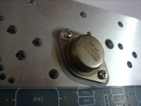
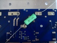
As in Post#1041, the source resistors can still be implemented w/o changing the pcb. Hope the 2 photos attached can clear my mumble jumble in Post#1041. The resistor can be even implemented on the component side which might be a bit crowded.
As in Post#1041, the source resistors can still be implemented w/o changing the pcb. Hope the 2 photos attached can clear my mumble jumble in Post#1041. The resistor can be even implemented on the component side which might be a bit crowded.
Attachments
If you read the technical notes that are in pdf somewhere, the claim by Goldmund is this particular amplifier topology does not require matched output devices.
TRANSISTOR SELECTION
Transistors have been selected for their minimum sonic thumbprint. The double inverted symmetrical topology makes the negative and positive part of the signal travel in the same type of transistors to symmetrize the non-linearity of these transitors.
The low coloration allows multiplication of this same kind of stage without the typical sound alteration.
The total symmetry and use of inverted transistors in each signal path provides high insensitivity to transistor matching. Replacement of a transistor doesn't effect the balance of the design nor the sound quality.
A single adjustment for each stage compensates for DC offset differences between modules so that a quick DC tuning is the only adjustment needed after a transistor or input module replacement.
Thanks BigPanda and Agisthos,
I read somwhere in the thread that they didnt need matching, but didnt realise it was from the manufacturer. Not sure how they get away with this, but they obviously do.
Im still undecided, but i would like to build it if it ever gets tested first and doesnt hiss or hum.
I read somwhere in the thread that they didnt need matching, but didnt realise it was from the manufacturer. Not sure how they get away with this, but they obviously do.
Im still undecided, but i would like to build it if it ever gets tested first and doesnt hiss or hum.
Source resistors are not needed, MOSFETS do NOT need to be matched in this schematic. I just really don't know how to be any more clear than this")
This issue was discussed here for countless times.
Please, Norbert, as the only real engineer* around here, would you please enlighten* the obviously uninformed* audience WHY this special schematic does not require source resistors? Just claiming it doesn't seems not to satisfy the unenlightened* audience here. I'm sure a detailed technical explanation would prevent this issue from popping up again and again.
*sarcasm
Lee:
Please do not kibitz on Nagys engineering skills and PERSONAL knowledge of this amplifiers unique topology. You have to nique up on it, to understand. Just read post 686 and the real deal at (WTF) and famous #666. That should sooth ALL concerns you or anyone might have. Besides you can just just jumper out where the Emitter Resistors would be if you do not want to use them, RIGHT...
Please do not kibitz on Nagys engineering skills and PERSONAL knowledge of this amplifiers unique topology. You have to nique up on it, to understand. Just read post 686 and the real deal at (WTF) and famous #666. That should sooth ALL concerns you or anyone might have. Besides you can just just jumper out where the Emitter Resistors would be if you do not want to use them, RIGHT...
Lee:
Besides you can just just jumper out where the Emitter Resistors would be if you do not want to use them, RIGHT...
Not now. The new PCB won't have source resistors.
........... I also at the time was on the search for the Holy Grail of amplifiers but unfortunately Goldmund was not it. Further along the way I discovered Pass but that is a different story...................
Jam
how dare you ....... ?
( should we see firecrackers all over the world ....... soon ? )

Hi Nagys,
If I were you, I won't even state the fact that the circuit doesn't need source resistor, you had done that too many times already. If there is a necessity, people can still add them. All I have to do is to show that if anyone wants to implement the resistor (if he think that can solve his problem), he can do so with the board. The board has allow the option (w/o bothering alex to change it again). Wouldn't that end the argument? You can do it your way w/o the resistors and they can have it their way to include them. Everybody is happy.
If I were you, I won't even state the fact that the circuit doesn't need source resistor, you had done that too many times already. If there is a necessity, people can still add them. All I have to do is to show that if anyone wants to implement the resistor (if he think that can solve his problem), he can do so with the board. The board has allow the option (w/o bothering alex to change it again). Wouldn't that end the argument? You can do it your way w/o the resistors and they can have it their way to include them. Everybody is happy.
Nagys
I hope that you're aware - in your arrogance - that you personally are responsible for every scorched output mosfet , which any delusion-ed DIYa certainly will have , obeying your "no need to match" approach .
you're personally responsible for any possible fire or electrical shock , resulted from malfunction .
repetitive claiming that sort of technical nonsense is just disgusting , at least in my book;
you're playing with both - people's money , and security .
Last edited:
Ok, this is post #666:
I read from there till post #686:
Still no explanation.
But I wonder Nagys had to repair so many broken Goldmund amps and had to replace transistors...
Btw: Everything was finished over 400 post ago as announced in post 661 already:
Why is the pcb not manufactured and a prototype built already???
Nagys announced countless times everything is finished now and 100% perfect...
Dougie085 - Why does something have to be 100% perfect? Isn't this a DIY forum? I'm assuming that the potential builders will at least understand the fundamentals of electric circuits and be fairly handy? So lets say one might have to substitute a part, or make something fit better on the board by drilling additional holes, or omitting a part, or modifying the tracks slightly with jumpers, etc. This is all part of the fun and part of building any circuit. This is not meant to be a production PCB.
This is a fairly simple amplifier, with minimum amount of parts. The PCB will no doubt work properly. Everything else is up to each individual builder.
I read from there till post #686:
Goldmund's tag line from 80s to 00s for the Mimesis series of amplifiers have always been that one can replace any transistor without matching it. I have repair numerous Goldmund amplifiers, never once did I match any transistors and never once did the amps not perform anything, but 100% like they should. This is no Hafler.
Still no explanation.
But I wonder Nagys had to repair so many broken Goldmund amps and had to replace transistors...
Btw: Everything was finished over 400 post ago as announced in post 661 already:
The circuit and PCB board is 100% correct and ready for prime time!
Why is the pcb not manufactured and a prototype built already???
Nagys announced countless times everything is finished now and 100% perfect...
Last edited:
Looking at this schematic, or any other for that matter, the MOSFETS "OBVIOUSLY" need to be matched, at least they have to be matched close enough. My mistake I'm still definitely against the source resistors. They're not needed. Just MATCH your MOSFETS! Most MOSFETS from a certain batch will probably already be close enough and no further matching will be required. In worst case scenario, source resistors can be installed as Bigpanda has suggested But that's a band aid and not a proper way of building an amplifier. Point of the story: MATCH your MOSFETS, or at least check them to see if they're already close enough.
Again, sorry to all those who I argued with before.
I'm still definitely against the source resistors. They're not needed. Just MATCH your MOSFETS! Most MOSFETS from a certain batch will probably already be close enough and no further matching will be required. In worst case scenario, source resistors can be installed as Bigpanda has suggested But that's a band aid and not a proper way of building an amplifier. Point of the story: MATCH your MOSFETS, or at least check them to see if they're already close enough.Again, sorry to all those who I argued with before.
- Home
- Amplifiers
- Solid State
- The Very Best Amplifier I Have Ever Heard!!!!