Hi guys,
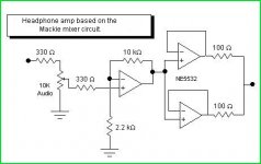
I have made an op amp headphone amp based around a cheap TL074 I had lying around. I did not have a rail splitter, so I used two of the four op amps available in this configuration -
The power supply op amps are connected in parallel. The rest of the circuit is of a pretty standard non inverting amp design, with a resistor and capacitor added in the feedback section for bass boost.
I am only getting a very average power output from this amp at the moment - I believe it's because of the op amp I am using but I am asking for help to confirm this. I tested the voltage and currect going through my headphones (32ohm cans) at maximum power before clipping (checked with a scope), at 60Hz. I got 1.6V @ 11.89mA, which is 19.024mW. This seems like a very low power output to me! If I replaced this chip with something like an OPA4227, Do you think I will get more power?
Would a 32ohm resistor connected to the op amps output help at all (maximum power transfer)?
Thanks a lot!
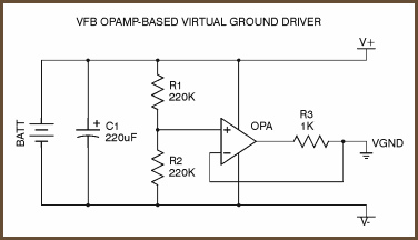
You have a couple of major problems. TL072 is nowhere near powerful enough to drive headphones, and the 1k resistors in your virtual 0V lines are not helping it's impedance and therefore ability to source/sink current - there is only so much negative feedback can do.
Switch to OPA134 and change the output resistors to something between 10 and 100 ohms.
Switch to OPA134 and change the output resistors to something between 10 and 100 ohms.
Yeah sorry I forgot to mention I took out that 1k resistor completely for that very reason, it was hindering performance massively. Thankfully the power supply op amps are perfectly stable without.
I have been looking at various op amp datasheets, and there seems not to be a 'max output current' or 'max output power' detail. What exactly are you looking for on these datasheets that tells you what the power handling of the device is? What are the power handling values of the TL072 and OPA134?
The circuit is wired around a DIL14 socket, and I cannot find an OPA4134 in a DIL14 package. Would the 4227 be OK?
Thanks for your help btw
TLC074 - look for the "C" in the part number - has higher output current and swings closer to the rails - I've recently used the duals in smt but should be available in quad pdip
as a CMOS device the TLC has rather high parasitic input C and is faster than the TL BiFet devices
there can be some stability problems depending on feedback resistor value and gain, ~ 10 pF feedback from output to -in usually works - they can be soldered directly to the chip pins before socketing to save on board mods
better ps bypass, gnding and series R or lossy bead inductor in output (outside of the feedback loop) may also be required for stability
watch the Vmax - only 16 V so use with just 1 "9V" battery, some unregulated "12 V" wall wart supplies could go too high too
Last edited:
You look in the data forWhat exactly are you looking for on these datasheets that tells you what the power handling of the device is? What are the power handling values of the TL072 and OPA134?
The circuit is wired around a DIL14 socket, and I cannot find an OPA4134 in a DIL14 package.
Supply Voltage
and often close there is
"Output current, max"
OPA2134 has at least 35 mA out.
About the DIL14.
Can't you make it two DIL8 and use two OPA2134 ?
This is what I should do.
OPA2134 has good output power, has been often seen as headphone amp,
has got a fair price and you can get it almost everywhere.
For 32 Ohm, one OPA2134 channel would be enough.
If we want more current out we can parallell the 2 channels in one OPA2134
and so get as much as 70 mA output current.
I have been looking at various op amp datasheets, and there seems not to be a 'max output current' or 'max output power' detail. What exactly are you looking for on these datasheets that tells you what the power handling of the device is? What are the power handling values of the TL072 and OPA134?
Short circuit current and power dissipation are always listed. Also it's a bit of an industry golden rule that the minimum load for TL072 is 2k.
lineup, The supply voltage doesnt have anything to do with the power handling or output current, and the problem I seem to be having is that there is rarely a 'Max. Output Current" characteristic documented in the datasheets. With regards to using a DIL8 package, I would basically have to start from scratch (the circuit is fully completed). That doesn't seem to be the best option when there are DIL14 chips knocking about that will do the job.
jcx, I didnt know about that chip, its short circuit current is rated at 57mA and 1600mW power dissipation. That sounds perfect for what I need, thanks for the info!
richie, How do you use the short circuit current parameter? As an example, bottom of page 5 in the TLC074 datasheet there are two current values:
http://docs-europe.origin.electrocomponents.com/webdocs/0c90/0900766b80c905f2.pdf
Short-circuit output current and output current. Would you mind explaining what usage these parameters are? (and also how they got the 'output current' value, the short circuit one is quite self explanatory).
Thanks again guys.
This is from page 12 of the TL072 opamp datasheet that I've got:
It shows that the output voltage collapses at a load of 100R.
w
An externally hosted image should be here but it was not working when we last tested it.
It shows that the output voltage collapses at a load of 100R.
w
Ahh how utterly useless this op amp is at driving low impedence headphones! Will I help the situation at all by adding a 32R resistor in series of the op amps output (I am assuming the output impedence of this op amp is very low) to transfer as much power as possible to the headphones? Will this really make much of a difference at all in the real world?
- Status
- This old topic is closed. If you want to reopen this topic, contact a moderator using the "Report Post" button.
- Home
- Amplifiers
- Solid State
- Poor power output, op amp based headphone amp.