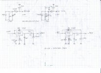
I have a suggestion to create bass by means of feed-back. Place a series capacitor resistor network accross R2. First lift the bass gently, use the same value resistor as R2 and add a cap by calculating to have the same Xc = R2 at at say 100 Hz. This way you will lift the bass by about 6 dB. If this does not help then half the resistor value.
Interesting idea.
As everybody searched very hard but no logical explanation could be found yet I have decided to check again the schematic starting all over again from the beginning.
Be patient I will come back asap I hope with more info. Stay tuned
")
I think it is the power supply. When the 42V droops under load it might feed through to the 36V rail too. As the source follower will not have perfect PSRR this injects a signal. The NFB loop will try to sort things out but might run out of steam. An oscilloscope on the supply rails would show if this is happening.
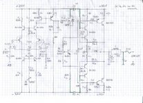
There s some miscalculations that had been done with this amp..
Current limitation will occur because of the limited drive ability
of the bc550/560 final cascodes in respect of the output stage
topology..
As an exemple, for 4A output current, the BC550/560 cascodes
must supply at least 25mA at the OPS base resistor point of
junction with R25 and R36...Those latter resistors should be increased
to about 470/680R, since with the original values, they drain much more
current than the OPS.
Of course, this will have an influence on the quiescent current
to an extent i can t readily estimate..
There s some miscalculations that had been done with this amp..
Current limitation will occur because of the limited drive ability
of the bc550/560 final cascodes in respect of the output stage
topology..
As an exemple, for 4A output current, the BC550/560 cascodes
must supply at least 25mA at the OPS base resistor point of
junction with R25 and R36...Those latter resistors should be increased
to about 470/680R, since with the original values, they drain much more
current than the OPS.
Of course, this will have an influence on the quiescent current
to an extent i can t readily estimate..
I can increase the quiescent current by playing on P2. Isn't it the same thing playing on P2 or changing value of R25, R26? I have already tried to increase quiescent current, the sound is a bit better but too much heat.
I can increase the quiescent current by playing on P2. Isn't it the same thing playing on P2 or changing value of R25, R26? I have already tried to increase quiescent current, the sound is a bit better but too much heat.
If you increase R25/36 , start with 220R in place of 100R as
in the original..
Make sure that the quiescent current is set to 0 before powering
with the new values.
Being too low at 100R, these resistors absorb much of the pre drivers
current capability..
Increasing the quiescent current will not solve the latter issue i mentionned,
quite the contrary...
You can also increase the gain of the output pseudo compound by reducing
R27/37 from 0.47 to 0.22 or 0.27R, but this will increase the quiescent current,
so in case you test also this mod, the advice of setting the said current to 0
before powering stand as well...
Last edited:
If you increase R25/36 , start with 220R in place of 100R as
in the original..
Make sure that the quiescent current is set to 0 before powering
with the new values.
Being too low at 100R, these resistors absorb much of the pre drivers
current capability..
Increasing the quiescent current will not solve the latter issue i mentionned,
quite the contrary...
You can also increase the gain of the output pseudo compound by reducing
R27/37 from 0.47 to 0.22 or 0.27R, but this will increase the quiescent current,
so in case you test also this mod, the advice of setting the said current to 0
before powering stand as well...
One channel of my amp is dead. Output transistors smoked.
Today I set quiescent current to ZERO, then replaced R25/36 from 100R to 220R on ONE channel (I was not completely convinced by this tweak). At power up the transformer made a loud vibration, I powered off immediatly. After check but I found out that the BD249/250 were dead
.I simulated the output stage, and changing the values to
220R did work although the quiescent current increase, but
it is possible with the original VBE multiplier to set it to a low
value.
The only problem is that the voltage divider around the VBE
multiplier is badly calculated as its range is way too large since
the max current can be set to 5A with R25/36 at 100R and as
much as 12A with the said resistors at 220R, so surely that
when triming the pot, there s a threshold where the current
rise abruptly...
Sorry for the bad things you experienced, hope i can help
resolve this issue..
NVD,
you did not use a mains bulb tester to power up your mains powered equipment after you modified it!!!!!!!
I usually use a 230V/110V transformer + fast fuses in transformer secondary to power up my circuits for the first time. But this time I was not enough cautious
, the tweak was not really a "big" tweak.I will replace output transistors by new ones and will take care before powering up, I have checked drivers transistors they seem OK but they may have suffered...
Thanks for your advice,
Fuses in the secondary will do absolutely nothing to protect your output devices, in fact even if they are after the caps directly in the rails they are unlikely to protect the output stage as silicon blows faster than wire.
Agree with you.
Fuses give me a "psychological" help to power-up. I am always anxious when powering up circuits for the first time. For me, fuses help to limit damages extent, stop them from propagating to other more expensive components (Transfos, PCB traces melting, etc). Silicon is usually "cheap" and easy to replace. A dead transfo is not the same thing.
The driver input just too weak for TIP41. This may a bootstrap design, the input gain tweaked(to have stronger gain with opamps) then oscillate, then bootstrap is removed (weak input stop oscillation caused by lower slewrate), then drivers getting too weak. That what I guess.
Bass need a strong kick of power, that mean strong enough driver signal.
Bass need a strong kick of power, that mean strong enough driver signal.
Sorry for not coming back earlier, I was busy fixing the amp, it almost makes me crazy.
You remember that I replaced R25/R36 from 100R to 220R and I fried the output BD249/250 while I was setting the biais current.
I removed the 220R and put back the 100R (R25/36) and replaced output BD249/250 by new ones and powered carefully this time.
I noticed that I have 23V DC at the output, the VN 88 and the BC560 (before the TIP41) are holt as hell. I checked and rechecked everything many many times in the output stage all are OK but I do not understand why I have this DC voltage at the output.
I wonder if the ouput BD's need to be matched as this amp is fully DC coupled?
- Status
- This old topic is closed. If you want to reopen this topic, contact a moderator using the "Report Post" button.
- Home
- Amplifiers
- Solid State
- How to improve bass response?