I wonder about the value of C3. Have you tried increasing it's value to see what, if any effect it has on the frequency response?
I doubt that changing output transistors will change the response.
It's possible that the amplifier was designed to have a limited low frequency response.
I doubt that changing output transistors will change the response.
It's possible that the amplifier was designed to have a limited low frequency response.
But there is nothing limiting the LF response - that is the mystery. However, we must remember that we are not chasing a puzzling frequency response measurement but a puzzling frequency response perception.
Charge can accumulate in the base region of a transistor and it takes a while to get rid of it when the transistor should be turning off. This can affect the HF end of the audio spectrum (and higher). It helps if the drive arrangements have some sort of pull-down for the base to remove the charge. I don't see how this could affect the LF end, as there is plenty of time for the charge to leak away.
I think I read somewhere once that low-order distortion can artificially boost the perception of bass. A very low note will not be reproduced by most speakers, and would not be heard by most ears even if the speakers could handle it. Low-order distortion introduces harmonics, which being higher in frequency (but still bass) are more easily heard. We hear more bass, and think the amp is better. In reality it is worse. This effect could work backwards - a new amp with less distortion could sound like it has less bass because it generates less of this pseudo-bass.
Hi Frank,
I did not played around with the value of C3. I have only played around with the value of C1 because it's a styroflex cap. The sound changes when I played around with the value of C1 but it did not improve much bass response. If the amp is designed to have limited LF response as you suggested we should find caps, filters, etc.. in order to limit the LF response but here we found no such things right?
Other caps in the circuit are of common cheap type so I did not played around with them because I guess that they have no effect on sound.
I planned to replace output transistors because on a more powerfull model (same brand) Toshiba transistors are used.
Hi Andrew,
I can check again the shematic but I am afraid that will not explain the lack of bass. As you can see there are few caps in this schematic and no caps in signal path for sure.
I have also increased the bias (50 ma original setting) to 200 ma the sound improve somewhat but not significantly, but the heat improved a lot so I decided to set back to original bias setting.
What puzzles me is how a DC coupled amp has less bass than a cap coupled amp?
I did not played around with the value of C3. I have only played around with the value of C1 because it's a styroflex cap. The sound changes when I played around with the value of C1 but it did not improve much bass response. If the amp is designed to have limited LF response as you suggested we should find caps, filters, etc.. in order to limit the LF response but here we found no such things right?
Other caps in the circuit are of common cheap type so I did not played around with them because I guess that they have no effect on sound.
I planned to replace output transistors because on a more powerfull model (same brand) Toshiba transistors are used.
Hi Andrew,
I can check again the shematic but I am afraid that will not explain the lack of bass. As you can see there are few caps in this schematic and no caps in signal path for sure.
I have also increased the bias (50 ma original setting) to 200 ma the sound improve somewhat but not significantly, but the heat improved a lot
so I decided to set back to original bias setting.What puzzles me is how a DC coupled amp has less bass than a cap coupled amp?
try connecting a 1.5V battery across the input.
Gain * 1.5V should appear at the output terminals.
reverse the battery and the output should change polarity.
This will show you if it is truly DC coupled. Dont do this with the speakers connected.
Is there any way you can send a few test tones into the amp ( 1k reference, 20, 40, 60 100 hz) and then measure there levels after each stage of the amp?
This may tell us where your losing the bass, and how much. (not to mention quieting the skeptics who think your hearing things)
Charge can accumulate in the base region of a transistor and it takes a while to get rid of it when the transistor should be turning off. This can affect the HF end of the audio spectrum (and higher). It helps if the drive arrangements have some sort of pull-down for the base to remove the charge. I don't see how this could affect the LF end, as there is plenty of time for the charge to leak away.
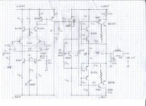
The result of using too high impedance for the drivers of the outputs and having no current path to discharge the base is that one OPT will turn on before the other turns off resulting in crossconduction at higher frequencies and destruction. I find it hard to believe there is no connection of the driver's (TIP41, 42) collector to something other than the base of the outputs, such as a resistor and cap between the bases of the OPT. The VN88 is just a follower for the first 'gain' stage, the mirror. The second gain stage is the feedback pair type output stage. I always refere to this type of complementary output stage as a 'ring of six'. I have found it can be hard to keep stable, but I have never gotten it to work unconditionally without somthing tying the output transistor bases together. Is there anything missing from the reverse engineered drawing?
Is it at all possible that there is an input circuitboard which might contain coupling caps?
Does the amplifier have audio input transformers?
This would be the very first time that I've seen a commercial-duty amplifier that is completely direct coupled. A little DC offset on the input could be disastrous to the loudspeakers.
Does the amplifier have audio input transformers?
This would be the very first time that I've seen a commercial-duty amplifier that is completely direct coupled. A little DC offset on the input could be disastrous to the loudspeakers.
I do not have all resistors values yet. Is it really necessary to have exact resistors value to analyze this problem?
I recall that this amp is not a DIY amp but commercial one, It worked more than 30 years like this and just failed because of PSU filtering capacitors broke down.
I recall that this amp is not a DIY amp but commercial one, It worked more than 30 years like this and just failed because of PSU filtering capacitors broke down.
Is it at all possible that there is an input circuitboard which might contain coupling caps?
Does the amplifier have audio input transformers?
This would be the very first time that I've seen a commercial-duty amplifier that is completely direct coupled. A little DC offset on the input could be disastrous to the loudspeakers.
Very good question Frank! I had the same idea than you this morning. There is indeed an inputs circuitboard in this amp, I checked with an ohmeter every input rca live wire to amp input and I found ZERO ohm without exception. No hidden coupling caps
. I will apply 1 volt DC to the input tomorrow.No audio input transformers.
There is protection for the speaker, protected by a fuse placed right after the coil, I didn't draw it because it has no effect on the very bass lack problem.
Hi CBS 240: Could you show me on the schematic where do you think that something is wrong in the reverse engineering drawing? It would help me to go direct on it.
I suspect the drivers are bias with more than just the base current of the output transistors, especially since the current gain of BD250 and BD249 vary so much. Besides, this would prevent the circuit from sucking out excess charge in the base of the outputs preventing them from turning off properly.

Attachments
May not be your problem buy I had this happen on a early project where the bias was adjusted to low. When I cranked up the bias I got lots of bass response. Do you have a variable potentiometer which you can use to test this situation. Some older potentiometers will lose the wiper after many years of use.
Tad
Tad
I have a suggestion to create bass by means of feed-back. Place a series capacitor resistor network accross R2. First lift the bass gently, use the same value resistor as R2 and add a cap by calculating to have the same Xc = R2 at at say 100 Hz. This way you will lift the bass by about 6 dB. If this does not help then half the resistor value.
I notice something else, the right hand side op-amp, is unbiased, its input is left floating. I do not think this is a good idea, what if the equipment plugged in is capacitive, this thing could be going anywhere. It should really be tide to ground by the same value as R1.
Hi all,
I will not be very active today here, I have disassembled the amp to check the schematic for the Nth times and making suggested tests.
PSU principle is quite straightforward:
PS for output stage: full wave bridge rectifying, filtered by 10 000uF on each rail (+/-42V)
PS for input stage: obtained from +/- 42V thru LM7815 and LM7915 with appropriate resistors arrangement to obtain +/-36 V
PS for TL072 (op amp): +/-15 V obtained from +/-36 V thru zeners
Il will post circuit diagram for the power supply ASAP, but I am quite sure you have enough info (with the experience you all have here) !
- Status
- This old topic is closed. If you want to reopen this topic, contact a moderator using the "Report Post" button.
- Home
- Amplifiers
- Solid State
- How to improve bass response?