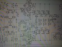
I have Parasound HCA-1000a with cross over distortions on both channel which is prominent when volume is low. So I decide to take Mr. John Curl advice to turn up the bias high. I connect meter across emitters of q119 and q122 and turn TVR1 and TVR2,-resulting no reading change from 0.0 mV ( both ch). I traced circuit which is slightly different than schematic. I found some thing odd about bias circuit..Can some one explain how this circuit works?
Birdyman
PS: How can I insert pdf file or image file to post???
Birdyman
PS: How can I insert pdf file or image file to post???
Last edited:
I have the schematic in pdf but it's over the attachment size limit even after compression. Any one knows a way to size down a pdf? Can't send by email due to the IT restriction at work. Will try when get home after work.
A very brief description about the biasing circuit would be like this:
the voltage between the base of Q111 - Q112 is 2*Vbe, or 1.1V, therefore the current over the resisters TVR101 and R116 is
Ib = (2*Vbe)/(R116 +TVR101) --- so trim the TVR101 will change Ib
base current of Q111 and Q112 is negligible compared to Ib, then bias voltage (between the base of Q115 - Q116) would be
Vb = Ib * (R114 + R115) + (2*Vbe)
Last edited:
Thanks for reply
Can you change bias voltages on your unit by adjusting TVR1 and TVR2?
I did not see any change of across-emitter-voltage on my unit on both channels. Initially, I thought faulty bias parts on both channel. All bias parts checked out to be normal. Then I look deeper on schematic, and found all trim pot are located between bases of 2 bias complementary transistors. I thought one trim pot should be located between collector to base to skew base voltage when it is turned (I can be wrong on this).
Thank you in advance
...........Then I look deeper on schematic, and found all trim pot are located between bases of 2 bias complementary transistors. I thought one trim pot should be located between collector to base to skew base voltage when it is turned (I can be wrong on this).
Thank you in advance
I definitely can trim the bias voltage in my unit.
The two pots are where they should be. the 200R pot serves for bias fine tune.
A 0.7mV between the base of Q115 - Q116 doesn't sound right. I'd turn off power and measure resistance between the base of Q115 - Q116, expecting a high resistance on a DMM. If I do get a high resistance then the 0.7mV would indicate the VAS transistors do not turn on at idle, meaning the DC setup with the input stage has problem.
Have you checked all the supply voltages (across all 47uF/63V caps) are good? How about Vbe of Q109 and Q110?
that is odd, could you measure the B-E voltage of the predriver transistor, it should be around.5V-.7V if they are "on" good and conducting. Try to measure first the output of the voltage regulator Q113, Q114 Emitter to ground, to establish that we are getting a supply to the front end, the 120mV-130mV your measuring might be a stray "voltages" especially if your using a DVM. If your unit has fusible resistors I would check them also if they are good. Check also for crack solders especially the voltage regulator.
What are 0.05k 100, FULL PSB type Cap?
This amp had dried PS caps which I replaced with 15000uf 63v.
Last night I found shorted c216 and c116 caps and they are the reason for unresponsive bias adjustments. With caps removed, now bias adjustment are working fine. Caps are labeled " 0.05k 100, FULL, PSB". ( two of these are used per channel, paralleled- one per each channel is bad) Can some one kindly explain what this is ?
Just finished recapping.
Now my HCA-1000a has 15000uf 80v caps and all new Nichicon FW or MZ caps but I am still waiting on four 0.05uf 100v PSB(Polystyren??) cap replacements. I ordered 250v 0.047uf and 0.056uf polypropylen caps from Mouser with 3 Non polar caps. All circuit is functional including bias. I am exciting to see this one working with my rest of stack as soon as all the parts and heat grease are replaced. Thank you very much for your help.
Now my HCA-1000a has 15000uf 80v caps and all new Nichicon FW or MZ caps but I am still waiting on four 0.05uf 100v PSB(Polystyren??) cap replacements. I ordered 250v 0.047uf and 0.056uf polypropylen caps from Mouser with 3 Non polar caps. All circuit is functional including bias. I am exciting to see this one working with my rest of stack as soon as all the parts and heat grease are replaced. Thank you very much for your help.
Birdyman, I am resurrecting this old topic to see if you are still around.
I have a 1000a with erractic bias on the right channel. I just removed the board and will be testing things out this evening.
In the meantime, would you mind posting the specific parts you used? I am aiming to just fix the bias issue but any other replacements that you thought worthwhile are welcome. Thanks!
- Status
- This old topic is closed. If you want to reopen this topic, contact a moderator using the "Report Post" button.
- Home
- Amplifiers
- Solid State
- Parasound HCA-1000a Bias Circuit Correct??