Dear Apex,
At 63 Vdc, mj's were getting warm after few minutes...maybe those were have to be put on heat sink ...
Thank you very much
MJE340/350 must have heatsink.
I suggest to use TOP3 outputs like SanKen 2SA1294/2SC3263.
For test use 150R/10W instead fuse in 220V AC line.
The pcb should be a little bit bigger,i´d say about 20% . I´ve searched forum pages and pages earlier written but i haven´t found this file,could someone suggest me a page/post where it was posted?
And yes,ALEX MM you´re amasing! I have allready saved two pcb/layouts of SR200 designed by you,and if i find it this would be third!
Thank you for all pcb-layouts given to us!
@44250:
see here for pcb with sanken http://www.diyaudio.com/forums/solid-state/173462-studio-reference-amplifier-29.html#post2562485
see here for pcb with sanken http://www.diyaudio.com/forums/solid-state/173462-studio-reference-amplifier-29.html#post2562485
@44250:
see here for pcb with sanken http://www.diyaudio.com/forums/solid-state/173462-studio-reference-amplifier-29.html#post2562485
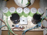
Thank you for trying,but this is the pcb http://i1266.photobucket.com/albums/jj521/lanukp/DSC_0008.jpg that i am looking for.
")
is this you looking for?
http://www.diyaudio.com/forums/solid-state/173462-studio-reference-amplifier-15.html#post2451276
http://www.diyaudio.com/forums/solid-state/173462-studio-reference-amplifier-15.html#post2451276
I'm sorry, and maybe this has been discussed before, but shouldn't Q11/BD139 be on the same heatsink as the output transistors?
Or as D. Self suggested on his book, bolted to one of the output transistors?
I hadn't paid attention to the pcbs before, so I hadn't realized that.
On a bipolar output amp there should be some tracking of the temperature, and the VBE transistor should do that.
Or as D. Self suggested on his book, bolted to one of the output transistors?
I hadn't paid attention to the pcbs before, so I hadn't realized that.
On a bipolar output amp there should be some tracking of the temperature, and the VBE transistor should do that.
The pcb should be a little bit bigger,i´d say about 20% . I´ve searched forum pages and pages earlier written but i haven´t found this file,could someone suggest me a page/post where it was posted?
And yes,ALEX MM you´re amasing! I have allready saved two pcb/layouts of SR200 designed by you,and if i find it this would be third!
Thank you for all pcb-layouts given to us!
This pcb is in post #154
Regards
Yes yes that is the one! I´ve started with searching from last to first page,that is why i haven´t found it. Thank you so much!
This pcb is in post #154
Regards
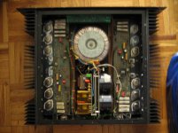
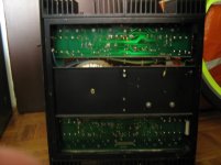
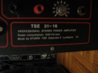
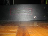
I allready have files for "SR200 V2" and "SR200 V2.3" (both done by alex mm) ,but i haven´t had this one with side mounted outputs. When i begin to do SR200 it will be V2.3 ,and i allready have donor for it,it is some unrepairable amplifier with working 2 x 53VAC 900VA transformer,side mounted heatsinks and good looking fabric metal box with 2 x 14 led power level indicator...more than half parts needed. If i find a picture of it i will post it.
Attachments
Last edited:
That i going to be APEX SR200,one fine day,this year!
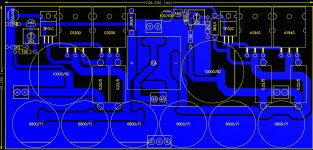
I suggest new pcb design for TO3 outputs like MJ15024/MJ15025, and use this L heatsink.
Nice spec.´s for MJ pair,but the price is more than double than 2SC5200/2SC1943. Would there be trouble if i use 2SC/2SA pairs on 4 Ohm load? If i calculated it well,there would not be trouble but i am not so sure in my calculations. I am messing RMS and Peak voltages with current through the output transistors and speaker. If i calculated well,for 200W on 8ohm there should be 40Vrms/56,4Vp and the current should be 5A. For the same output voltage on 4Ohm load there would be 10A of current. On output transistors there would be 35V if i use 40Vrms or 350W of disipation for three of them (116W/transistor). If i use Vp value (56,4Vp) there would be 18,6V /10A or 186W for all of them(62W/transistor)
Is there any good from my calculations,and if there is,what value of voltage should i use;Vrms or Vp?
(sorry for beginers questions,just don´t know how to find out...)
Is there any good from my calculations,and if there is,what value of voltage should i use;Vrms or Vp?
(sorry for beginers questions,just don´t know how to find out...)
Hello,
OK, I have not paralleled the resistor to inductor, Will do it.
Alex I mounted the transistors, and connected to psu.
Fired up and connected to mobile phone---- No sound.
Mobile disconnected Touch input pin with hand it make lots of noise and 22e resistor on psu gets extremely hot.
Checked all the connections.
Checked for shorts- No shorts.
Checked transistors for short to heat Sink- No short.
Disconnected speaker gnd from psu gnd- Psu resistor does not get hot, Connect again gets hot.
what Could be the problem.
And how do I Measure and adjust the Bias, Please Show exact procedure, I have never done it before.
Sir,
Plz share its schematic
Dear Mr. Apex,
I am sorry .
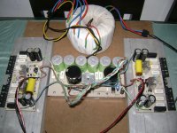
I plan to post it here after I write some review about it, with some measurements I conducted. I have just finished and test it for some hours. The wiring is so mess...
I will post it soon..
Thank you so much for sharing your amplifier designs...
Best regards,
Arif Budiyanto
I am sorry .
I plan to post it here after I write some review about it, with some measurements I conducted. I have just finished and test it for some hours. The wiring is so mess...
I will post it soon..
Thank you so much for sharing your amplifier designs...
Best regards,
Arif Budiyanto
Last edited:
Dear Mr. Apex,
I am sorry .
I plan to post it here after I write some review about it, with some measurements I conducted. I have just finished and test it for some hours. The wiring is so mess...
I will post it soon..
Thank you so much for sharing your amplifier designs...
Best regards,
Arif Budiyanto
Nice work, can you share your PSU-10 pcb design?
Regards
What is the maximum supply for this SR200, I have some 10.000uf/80v caps?
Thank you
Best regards,
Arif
Maximum supply for SR200 is +/-75V
Regards
- Home
- Amplifiers
- Solid State
- Studio Reference Amplifier