That's real DIY
Congratulations Mr. Mile!
Thimios.
Be welcome
Aw man, now I have another amp to build.
at least you have a part-list to make it a little bit easier
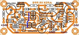
only thing you should pay attention ir 560r in series with relay - it depends on relay coil resistance and it is not "must be" 560r - it should have enough resistance (and power) to get relay voltage to it´s coil and 560r is a solid starting point for 12V relay´s.
good luck with SR150 DIY!
hi apex sir, is c5200 and a1943 good transistor?there is c5200 printed on your sr 800 and on h900 also.it show that you used that transistor in your amp.i also use this pair in h900 but after one hour they are start to down now i will replace it with on semi device.in my town local pa amp manufacture also using c5200 for 1500w channel.what is truth about these transistor?what is your thinking.please share with love.this is very important for all diy so please reply.
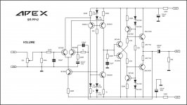
SR250 with new OS
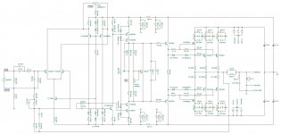
In attachments you will find TinaTI simulation files,
SR150, SR150H and the latest variations SR150LBH LinearBipolarHybrid
with Mosfet at the output,
together with the complementary pair 1943/5200.
They are biased: mosfet@250mA, bipolars@cca 50mA each,
and must be closely matched for even current distribution.
At Mosfet gates is a linearisation stage in some current mirror variation
which design is from our forum member MacolaKG here at local forum DIY Audio Projects
The whole output stage is in the very strong local FB
and output stage curve parameter from such type output is pure line y = K * x,
The predrivers are biased also in ClassA@25mA,
Feel free to take a journey with doose files into simulation world and look at amps parameters...
Regards
Dragan100
SR250H,in progress:
(there will be lateral SR250, and smaller versions irfp / 2sk-sj with one pair of bipolar transistors in output-4 versions in total)
Attachments
SR250H,in progress:
(there will be lateral SR250, and smaller versions irfp / 2sk-sj with one pair of bipolar transistors in output-4 versions in total)
not checked...
the point would be to play a bit in order to get first watt or two in a-class,make mosfet to play to about 30-35W / 8r and than to get all the help needed from output BJT pair. i believe that i will build smaler lateral version because it will give me enough power and i have output transistors. before i do any pcb´s i must check out if it is matching schematics,and to adjust resistors in bias circuite. for lateral mosfets there should be a little less Ugs and bias transistor probably will not be needed but practise will tell.
Attachments
-
MiM amp.zip570.2 KB · Views: 472
-
 hibrid zM.GIF177.9 KB · Views: 266
 -
 hibrid z L.GIF206.9 KB · Views: 249
 -
 hibrid z.GIF207.8 KB · Views: 252
 -
 hibrid ML.GIF205 KB · Views: 289
 -
 hibrid M.GIF203 KB · Views: 312
 -
 hibrid L.GIF241.2 KB · Views: 367
 -
 hibrid.GIF241.8 KB · Views: 1,445
 -
 SR250H.JPG271.2 KB · Views: 654
 -
 hibrid zL.GIF178.2 KB · Views: 301
Last edited:
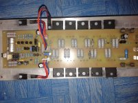
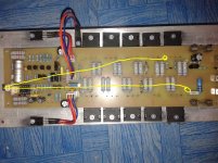
Are the cable wiring ok ?
Need advice and lighten...
Just need wire to connect two point with gnd. Pcb layout was modified from Alexmm layout just to fit extra OP. Layout for protect and zobel was done keeping in mind double side copper board that I had back then.
Attachments
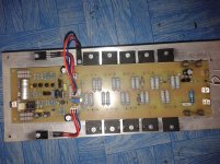
backside
Cable jumper on the backside sir...
How mA for the bias i suppose ti give sir?
Just need wire to connect two point with gnd. Pcb layout was modified from Alexmm layout just to fit extra OP. Layout for protect and zobel was done keeping in mind double side copper board that I had back then.
Cable jumper on the backside sir...
How mA for the bias i suppose ti give sir?
Last edited:
not checked...
-the point would be to play a bit in order to get first watt or two in a-class,make mosfet to play to about 30-35W / 8r
and than to get all the help needed from output BJT pair.
-for lateral mosfets there should be a little less Ugs and bias transistor probably will not be needed but practise will tell.
Regard 44250, fast progress!!!
For V_be biasing circuit with laterals in output we`ll need only R16 - 150R and P1 - 500R multiturn (10 turns) trimmer pot.
Because for laterals output pair in hybrid version with their positive temp drift we will eliminate:
-T14 V_be bipolar
-R15 put 0R or short
with 10-11mA biasing current (VAS CCS) we`ll have
-min U_bias 1,5V (150R)
-max U_bias cca 7V (150R + 500R trim.pot)
and we needs cca ( 2x 1,1V (for Ugs treshold typ laterals) + 2x U_be (for U_be drivers) + 2x deltaU_R (for R13, R14)) = TOT typ 3,7 - 3,9V
-start biasing with P1 at 0R and gradually turning trimmer with DMM on mVDC range over R8 (or R7 - 0R39) and find 55mV - 60mVDC reading,
this is minimum bias current for output mosfets pair - 150mA.
Both bipolars output pairs are in STDBY mode, they need about 0,7-0,75V treshold voltage over R7-R8 for starts conducting.
With bias current cca 250mA we have:
-classA region with "mosfet solo" - cca 2Wrms/8R0
-classAB with "mosfet solo" - cca 16-18Wrms/8R0 with R7, R8 - 0R39, and with 0R33 we get almost 25-30Wrms/8R0
If you have large heatsink, tray biasing with more current, you will have more power in classA push-pull region and also minor THD.
Don`t exaggerate, the THD improves only slightly, on 3-4th decimals range
The drivers MJE340/350 are biased also in classA @15mA (R6 = 560R) or with cca 25mA (R6 = 470R)
and in my opinion is enough current "storage" for driving mosfets gate charge + R_gs 2K2 without leaving classA.
R6 must be at least 1/2W for 560R or 1W for 470R.
-classAB hybrid 150Wrms/8R0 and klipping occurre/appears at 175-180Wrms/8R0 with PS +/-55VDC and +/-70VDC for input+VAS section.
Dragan
first one to be checked will be lateral version with one pair of BJT in output,this should be latest files. when i become sure i will post other files:
Attachments
PCB??
thanks
regard
Does someone build this project??? where is post/threads, i want to try this.Preamp or headphone amp.
thanks
regard
Hi dobrivoje, beautiful work!You're welcome, Mile.
I'm not in position to build anything, so I spend my free time drawing pcbs.
Can you draw a pcb for this Apex buffer? Many Apex amplifiers can be used with this.
Attachments
Last edited:
- Home
- Amplifiers
- Solid State
- Studio Reference Amplifier