Apex sr 200 studio referance.
cintinua
cintinua
Attachments
-
 DSC06614.JPG575.5 KB · Views: 1,302
 -
 DSC06624.JPG598.4 KB · Views: 77
 -
 DSC06623.JPG585.7 KB · Views: 56
 -
 DSC06622.JPG586.5 KB · Views: 53
 -
 DSC06620.JPG586.3 KB · Views: 61
 -
 DSC06619.JPG574.9 KB · Views: 58
 -
 DSC06618.JPG595 KB · Views: 878
 -
 DSC06617.JPG599.7 KB · Views: 945
 -
 DSC06616.JPG591.3 KB · Views: 1,046
 -
 DSC06615.JPG581.8 KB · Views: 1,148
Apex sr 200 studio referance.
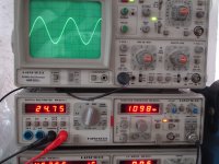
All tests as follows
Usys.+/-45v
Cpsu.51.000uf/rail.
out.transistors 2x2sc3264
2x2sa1295
idle current.45ma(25mv on 0.33R)
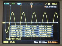
Vinp. 570mvrms
Vout. 24.6VRMS
Rload 8R
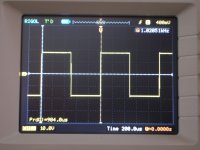
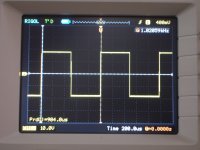
Finaly 3 other photos
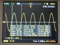
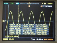
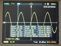
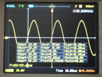
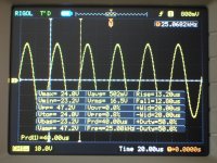
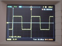
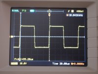
1) 1KHz behind zobel
2) 1KHz after zobel
3) 10KHz behind zobel
4) 10KHz after zobel.
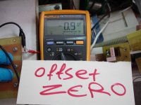
5) zero offset.
6)570mv inp ,24v out just pehind cliping
All tests as follows
Usys.+/-45v
Cpsu.51.000uf/rail.
out.transistors 2x2sc3264
2x2sa1295
idle current.45ma(25mv on 0.33R)
Vinp. 570mvrms
Vout. 24.6VRMS
Rload 8R
Finaly 3 other photos
1) 1KHz behind zobel
2) 1KHz after zobel
3) 10KHz behind zobel
4) 10KHz after zobel.
5) zero offset.
6)570mv inp ,24v out just pehind cliping
Attachments
Last edited:
All tests as follows
Usys.+/-45v
Cpsu.51.000uf/rail.
out.transistors 2x2sc3264
2x2sa1295
idle current.45ma(25mv on 0.33R)
Vinp. 570mvrms
Vout. 24.6VRMS
Rload 8R
Finaly 3 other photos
1) 1KHz behind zobel
2) 1KHz after zobel
3) 10KHz behind zobel
4) 10KHz after zobel.
5) zero offset.
6)570mv inp ,24v out just pehind cliping
Thanks for your work and all this tests.
Regards
Thanks for your work and all this tests.
Regards
I should thank you Sr for the fantastic amplifier gave us.
I hope you are always healthy and always with us.
")
Best regards.
Thimios.
Agrinio Greece.
Last edited:
I also want to thank everyone who helped in addressing the problem.
Regards.
Thanks to 'alex mm' for pcb design and what is your final circuit?
Apex sr 200 studio referance.
Thank you especially Mr.Alex mm.
Without your's printed circuit board construction would be impossible.
Mr Apex just missed my own question.
This time circuit is with R11=8K2
R18=2K2
added 18pf between collector Q9 base Q2
Theese all modifications.
Is it necessary to keep them all?
Regards.
Oh I'm literally unpardonable for this my omissionThanks to 'alex mm' for pcb design and what is your final circuit?
Thank you especially Mr.Alex mm.
Without your's printed circuit board construction would be impossible.
Mr Apex just missed my own question.
This time circuit is with R11=8K2
R18=2K2
added 18pf between collector Q9 base Q2
Theese all modifications.
Is it necessary to keep them all?
Regards.
Last edited:
Oh I'm literally unpardonable for this my omission
Thank you especially Mr.Alex mm.
Without your's printed circuit board construction would be impossible.
Mr Apex just missed my own question.
This time circuit is with R11=8K2
R18=2K2
added 18pf between collector Q9 base Q2
Theese all modifications.
Is it necessary to keep them all?
Regards.
It's ok and you must use heatsinks for MJE340/350.
Regards
sr200 studio refer.
I'm on the road for version 3.2 but at this time haven't many parts
Thanks Mr Apex
Thanks Mr Alex mm
It's ok and you must use heatsinks for MJE340/350.
Regards
I'm on the road for version 3.2 but at this time haven't many parts
Thanks Mr Apex
Thanks Mr Alex mm
Attachments

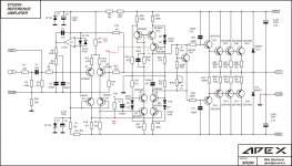
Dear Adrew this is shematic last modified by Apex. Red values are the modifications.Thim,
can you post your final schematic? Add notes on what values you changed to reach that success.
And finally what values did not work for your build.
Keep in mind that original schematic is functional also with a little problem an overshot
probably.
Attachments
Last edited:
I'm on the road for version 3.2 but at this time haven't many parts
Thanks Mr Apex
Thanks Mr Alex mm
A romantic version of SR200
Good luck!
Last edited:
sr200 studio refer.
Thanks wiljj78A romantic version of SR200
Good luck!
sr200 studio refer.
Just as befits a reference amplifier.
Thanks Mr.
Very artistic picture of SR200
Just as befits a reference amplifier.
Thanks Mr.
Hi Mr Apex.
I have made a zobel just with i had this time and test again.
first picture is for +/-35v rail 50mv on 0.33r idle current .
out.14vRMS/8R at 11Khz.Please take a look.
Second picture is under same conditions
+/-35v
1 pair 2sc5200/1943
50mv on 0.33
450mv inp./1khz just before start symetrical cliping
19vRMS out/8r
and the draft zobel
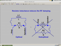
For an output zobel, you take the output/speaker leads from directly across the resistor, not the inductor. This is because the resistor needs to have as little series inductance as possible to increase damping at RF. Stray inductance of the inductor leads, as you may have guessed, does not matter. I would use carbon comp for this resistor if possible.
Last edited:
sr200 studio refer.
Well i did not understand . In your diagrame Zobel is in parallel to the loudspeaker?
As you say non inductive resistors is the must for that circuits but if you haven't ?
any chance to see a drawing of this
zobel..inductor...I dont understand what you are saying
(zobel cap/resistor is in parallel with output/speaker, and inductor/resistor would be in series)
Well i did not understand . In your diagrame Zobel is in parallel to the loudspeaker?
As you say non inductive resistors is the must for that circuits but if you haven't ?
Last edited:
- Home
- Amplifiers
- Solid State
- Studio Reference Amplifier