I too would refer to this as an output driven bootstrap to increase the front end supply rail voltage and help prevent front end clipping when signal voltages are high.Yes, there are a time constant...
Bootstrap circuit or Bootstrap Voltage Source is formed "slowly" by this time constant
RC_charg = (1K+100R)*4,7uF ... in few miliseconds,
but it is formed (the bootstrap voltage) already and long before the output stage demands a higher voltage driver swing
to put per-se voltage swing almost to the rails.
Bootstrap is then acting like a voltage source
(and for brief time we can say (quasi)constant) with 1K limiting resistor towards input/front stage with 35mJ @cca120VDC energy storage,
so if we need some higher energy demands say predominant @100Hz bas with some other mid-high freq superponed but not that amplitude levels,
with PSU +/-60VDC, with IPS demands for 72VDC (to fully drive the out stage),
and with bootstrap voltage "floating" around 120VDC,
the bootstraping can deliver almost 50mApeak to IPS,
and there are plenty current reserves in the bootstrap background waiting for delivery
Try this, with overvoltage protection towards fPS/front stage:
Zener voltage= maxU_rail + 15V
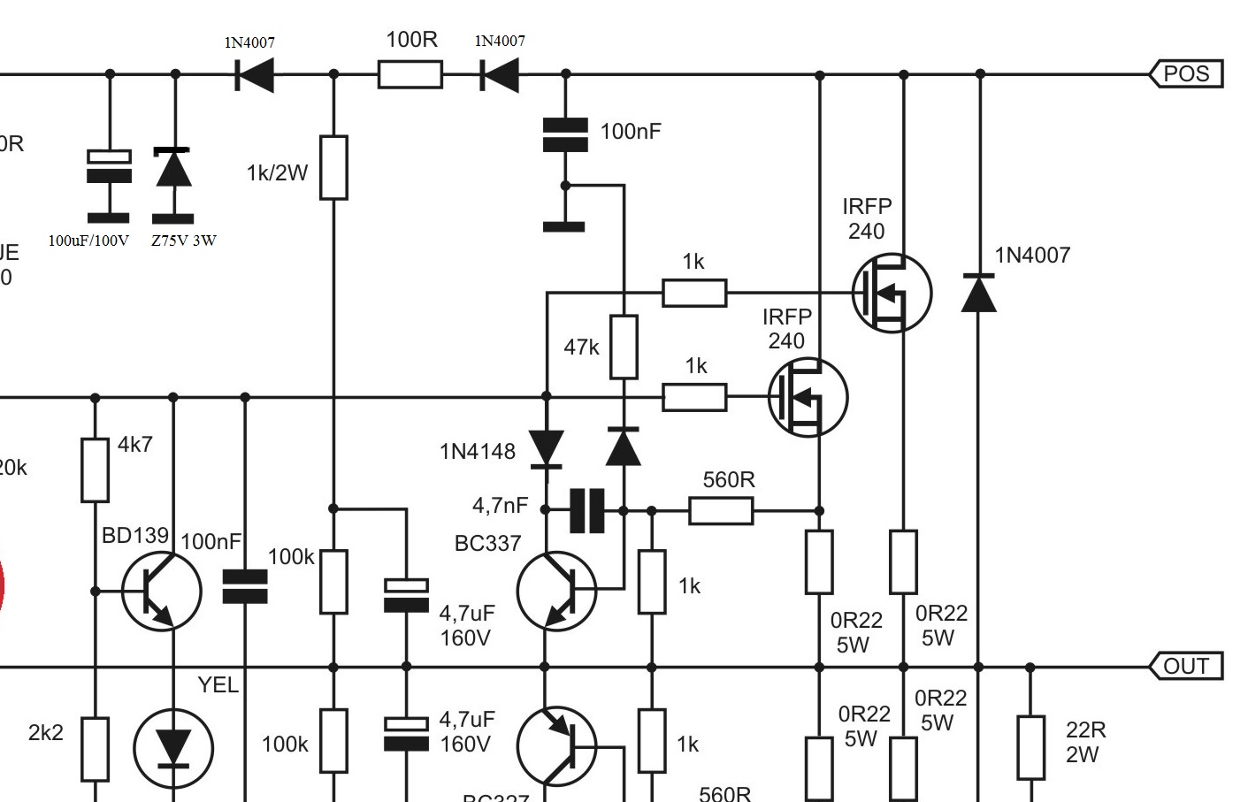
The 1k0 & 4u7F time constant is 4.7ms. i.e. the capacitor is charged to ~63% of supply rail voltage in ~4.7ms. The resistor suffers high current for <2ms. Will a 1k0 600mW resistor survive this without damage?
Will a ¼W resistor survive this? It's a simple experiment. Try it on a plug board. Try is one hundred times discharging between each charge.
Last edited:
Time constant for 4,7uF and 100R is IMO too small for low frequencies. Diodes in series with 100R resistors should help, or increasing capacity.
look at LEM bootstrap version and their values
Attachments
I
The 1k0 & 4u7F time constant is 4.7ms. i.e. the capacitor is charged to ~63% of supply rail voltage in ~4.7ms. The resistor suffers high current for <2ms. Will a 1k0 600mW resistor survive this without damage?
Will a ¼W resistor survive this? It's a simple experiment. Try it on a plug board. Try is one hundred times discharging between each charge.
Hi, AndrewT
-1K0 2W (45mArms continuous current)
and 100R 1/4W (50mArms continuous current) are on the shematic
-Resistor Short Time Overload: IEC 60115-1 4.13 (2.5 times RCWV for 5 Sec) and 5sec are (xxx)msec, that is 250mArms/5sec
-and this is not "lab (power) signal generator" to perform almost at max levels (to the clipping) all the time
")
-and this is not PA to "abbuse it to oblivion"
this is simple "Studio referrence amplifier" thread
EDIT:
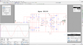
Ups...,I forgot the shortcut to Kuntermans simulation, we can clearly see what is happening to both resistors and bootstrap cap
http://www.diyaudio.com/forums/atta...1472356426-studio-reference-amplifier-vpp.png
Last edited:
take a look to this variant off output driven bootstraping
DIY Electronic projects
DIY Electronic projects
APEX FR100 Layout v1.1
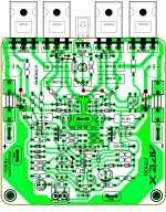
okay revised, adding a connection to ground with j5.
Thanks Terry.
Kuntarman,
You're missing a ground connection.
okay revised, adding a connection to ground with j5.
Thanks Terry.
Attachments
1k gate stoppers are pretty high value - is there a reason they are so much bigger than usual 220R? Should the 4.7u 160v caps be film caps as they look like they are in the audio signal path.
I am curious how this sounds compared to FH11/12 when you guys have a chance to listen.
I am curious how this sounds compared to FH11/12 when you guys have a chance to listen.
I am not sure what you are trying to tell us.Hi, AndrewT
-1K0 2W (45mArms continuous current)
and 100R 1/4W (50mArms continuous current) are on the shematic
-Resistor Short Time Overload: IEC 60115-1 4.13 (2.5 times RCWV for 5 Sec) and 5sec are (xxx)msec, that is 250mArms/5sec
-and this is not "lab (power) signal generator" to perform almost at max levels (to the clipping) all the time
-and this is not PA to "abbuse it to oblivion"
this is simple "Studio referrence amplifier" thread
EDIT:
Ups...,I forgot the shortcut to Kuntermans simulation, we can clearly see what is happening to both resistors and bootstrap cap
http://www.diyaudio.com/forums/atta...1472356426-studio-reference-amplifier-vpp.png
I can see 100r + 1k0 + 100k in series defining the continuous current flowing to the output node.
If the output node were at zero volts, then the continuous current is Vsupply/{100+1000+100000} = Vsupply /101100.
For a 75Vsupply the max continuous current is 0.742mA
The continuous dissipation would be 0.000742²*1000 = 0.55mW in the 1k0 resistor. For continuous duty a 60mW smd 603 is plenty big enough.
The charging time constant is set mostly by the the 100r & the 1k0, the 100k has virtually no effect.
The bulk of the high charging pulse has happened in less than 2ms. I can't see how you arrive at 5s.
Resistor Short Time Overload: IEC 60115-1 4.13 (2.5 times RCWV for 5 Sec) and 5sec
I am not sure what you are trying to tell us.
I can see 100r + 1k0 + 100k in series defining the continuous current flowing to the output node.
100K is bleeder for 4,7uF
Vsupply /1100 = max I_Cboot (when is tot discarged)If the output node were at zero volts, then the continuous current is Vsupply/{100+1000+100000} = Vsupply /101100.
For a 75Vsupply the max continuous current is 0.742mA
RE-read your posts, and then my answers tu your specific questions!The continuous dissipation would be 0.000742²*1000 = 0.55mW in the 1k0 resistor. For continuous duty a 60mW smd 603 is plenty big enough.
The charging time constant is set mostly by the the 100r & the 1k0, the 100k has virtually no effect.
The bulk of the high charging pulse has happened in less than 2ms. I can't see how you arrive at 5s.
Will a 1k0 600mW resistor survive this without damage?
Will a ¼W resistor survive this?
The Resistor Short Time Overload: normativ:
IEC 60115-1 4.13 (2.5 times RCWV for 5 Sec), and yes, they will survive!!!
And yes, high charging pulses will happened in less than 2ms or even shorter time and they are limmited with 1K1, so the spec. for the two resistors are OK! (2W, and 1/4W)
I can now understand.
Looks like we are saying almost the same thing.
The difference is you say use a 2W resistor, whereas I say test it on a plug board with a ¼W resistor and if that fails too soon , then swap in a ½W or 600mW resistor.
I don't see the need for a 2W resistor to charge up a 4u7F capacitor.
Looks like we are saying almost the same thing.
The difference is you say use a 2W resistor, whereas I say test it on a plug board with a ¼W resistor and if that fails too soon , then swap in a ½W or 600mW resistor.
I don't see the need for a 2W resistor to charge up a 4u7F capacitor.
Last edited:
Hi, AndrewT,I can now understand.
Looks like we are saying almost the same thing.
The difference is you say use a 2W resistor, whereas I say test it on a plug board with a ¼W resistor and if that fails too soon , then swap in a ½W or 600mW resistor.
I don't see the need for a 2W resistor to charge up a 4u7F capacitor.
glad to hear that we are saying almost the same things!
If we stay with low output levels, bootstraping has little or no work,
but with higher output levels works hardly, so way having a very hot element on PCB near term.sensitive elkos,
other semicond. with their temp drift, ...shorten their lifespan...
If I chose bootstrapping instead of an additional power supply for the front stage,
I would rather install even two resistors 470-560R/2W instead of one 1K-1K2/2W in the bootstrap circuit,
this would increase the area of cooling, the heat would be spread across a larger PCB surface.
And pumping hard an 4,7uF with almost rail voltage (with cca 60-70VDC) through 1K1, we quickly come near some W of average term.disipation.
Fortunately, this happens only in the extreme situations (high output voltage swing) and if I repeat myself this is not a PA amplifier.
You can replace 1N4007 diode in series with 100R with one 12V zener , the same orientation (cathode to 100R). And omit second 1N4007 and 75V zener.
There are variety of bootstrapping circuits with additional limiters (voltage and current), with different charging and discharging pats...
Try it in the simulator and find how high voltage levels we can achieve
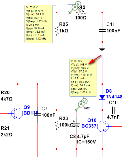
Look at Kuntarmans simulation (post #2093) results
-108Vpeak with 62VDC rails
-100mApeak inrush current (instant/pulse)
-35mArms on 1K resistor ( 1,2W term.disip. )
...
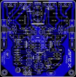
hello guys my layout came out kind like weird looking I will see if I can completed and check for bugs "errata" then if some one want the Sprint file let me know
Best Regards
Juan
I will see if I can completed and check for bugs "errata" then if some one want the Sprint file let me know Best Regards
Juan
Attachments
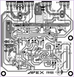
hello guys my layout came out kind like weird looking
Best Regards
Juan
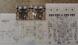
Hi Juan,i see an advanced pcb this time!
I didn't searce for bugs but i like the way you arrangement the power supply and input cables.

Make the same with yours other pcb.
Hi Juan,i see an advanced pcb this time!
I didn't searce for bugs but i like the way you arrangement the power supply and input cables.
Make the same with yours other pcb.
thanks thimios
I will search for bugs before post final I already simulated with multisim 14 and I believe responds really well also I will to see if I can eliminate some jumpers might be difficult but if I see too hard to do I will just then tweaked just a bit more Regards
Juan
okay revised, adding a connection to ground with j5.
Thanks Terry.
I believe the yellow LED is reversed.
I have started the FR100. Just need to attach the outputs and vbe multiplier. I should have it powered up tomorrow.
Kuntarman,
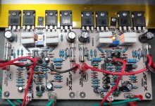
I hope you don't mind. I used your Sprint file but moved some things around to utilize parts I had in my bins. I also added a couple 220uF caps on the rails just for kicks.
Blessings, Terry
Kuntarman,
I hope you don't mind. I used your Sprint file but moved some things around to utilize parts I had in my bins. I also added a couple 220uF caps on the rails just for kicks.
Blessings, Terry
Attachments
I have started the FR100. Just need to attach the outputs and vbe multiplier. I should have it powered up tomorrow.
Kuntarman,
I hope you don't mind. I used your Sprint file but moved some things around to utilize parts I had in my bins. I also added a couple 220uF caps on the rails just for kicks.
Blessings, Terry
Nice work.
Regards
Sorry, I took the day off yesterday. I fired it up today. Nice! I hfe matched the small transistors and I have 2mV offset one channel and 3mV on the other. I used a 2k trimmer and it very ample for adjusting the bias. I have it set to 90mA. Square waves are very clean. Just a slight rounding of the leading edge at 20khz. 100hz is almost flat and the bass response reveals this. Bass is deep and tight. Really sounds great and is very stable. Kuntarman's layout is good except for the LED needing to be inverted.
Another winner from APEX.
Blessings, Terry
Another winner from APEX.
Blessings, Terry
Attachments
- Home
- Amplifiers
- Solid State
- Studio Reference Amplifier