
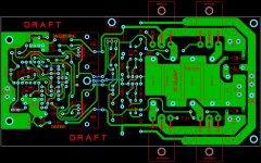
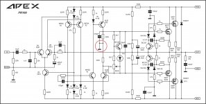
APEX FR100 Layout
Please be corrected if there is something wrong with this layout because i are beginner.
Regards,
Very nice layout and thanks for sprint file.
Regards,
Sonal Kunal
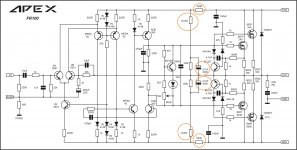
I've got a couple questions about the FR100. There is a 100R resistor in each rail ahead of the front end. No watt designation so I would assume 1/4W. However after that there are 1k/2W resistors connecting to 100k/.250W ending at the output. There are also 4u7/160V caps.
Can one of you help me understand how the 1k is 2w when it follows a 100R/.250W resistor?
Also why are those two caps 160V when the rails are likely +-50V?
Thanks, Terry
Can one of you help me understand how the 1k is 2w when it follows a 100R/.250W resistor?
Also why are those two caps 160V when the rails are likely +-50V?
Thanks, Terry
Attachments
I'm trying to learn. I'm not being coy. I don't understand why 160V is warranted.You haven't take in account the A.C out voltage.
I also don't understand how the 2W resistor comes into play. What does this part of the circuit do? Just looking to understand better.
Last edited:
I'm trying to learn. I'm not being coy. I don't understand why 160V is warranted.
I also don't understand how the 2W resistor comes into play. What does this part of the circuit do? Just looking to understand better.
Maybe it's to enforce 0V DC offset on the output?
2W for 1k resistors, because when starting and 4.7uF caps are being charged, they can be treated as short, so there will be
full rail voltage on these resistors?
E.g. for 50V rails that would be 2.5W (for very short time).
Last edited:
Yes but wouldn't that same current be going through the 1/4w 100R resistor?Maybe it's to enforce 0V DC offset on the output?
2W for 1k resistors, because when starting and 4.7uF caps are being charged, they can be treated as short, so there will be
full rail voltage on these resistors?
E.g. for 50V rails that would be 2.5W (for very short time).
Yes but wouldn't that same current be going through the 1/4w 100R resistor?
50mA going through 100 ohm generates (from Ohm): 5V * 50mA = 0.25W
I see. I should have done the math. Still, what does this circuit do? It is not connected anything other than the rails and the output.
My guess it is to enforce 0V DC offset on the output - 'brute force' method instead of having DC offset trimmer added somewhere nearby LTP.
I've got a couple questions about the FR100. There is a 100R resistor in each rail ahead of the front end. No watt designation so I would assume 1/4W. However after that there are 1k/2W resistors connecting to 100k/.250W ending at the output. There are also 4u7/160V caps.
Can one of you help me understand how the 1k is 2w when it follows a 100R/.250W resistor?
Also why are those two caps 160V when the rails are likely +-50V?
Thanks, Terry
I think it's for pushing IPS voltage few volt higher than OPS. You have look at voltage swing of output mosfets and charging, discharging of 4u7/160V caps.
It looks like it may be a virtual ground circuit for those who don't have a center tap on their transformers. They can be very specific to the circuit though because they can cause startup behavior problems. They will not force 0VDC offset.
Other than that, I see no point.
Other than that, I see no point.
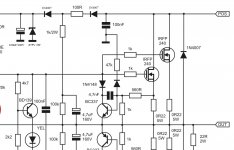
Apex FR100 Multisim
May be with this simulation can help you to understand.
Regards,
I've got a couple questions about the FR100. There is a 100R resistor in each rail ahead of the front end. No watt designation so I would assume 1/4W. However after that there are 1k/2W resistors connecting to 100k/.250W ending at the output. There are also 4u7/160V caps.
Can one of you help me understand how the 1k is 2w when it follows a 100R/.250W resistor?
Also why are those two caps 160V when the rails are likely +-50V?
Thanks, Terry
May be with this simulation can help you to understand.
Regards,
Attachments
It looks like bootstrap (suplly voltage is than signal dependant) circuit for input and VAS, in order to increase output swing. But values are very "strange".I've got a couple questions about the FR100. There is a 100R resistor in each rail ahead of the front end. No watt designation so I would assume 1/4W. However after that there are 1k/2W resistors connecting to 100k/.250W ending at the output. There are also 4u7/160V caps.
Can one of you help me understand how the 1k is 2w when it follows a 100R/.250W resistor?
Also why are those two caps 160V when the rails are likely +-50V?
Thanks, Terry
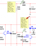
1K/2W + 4,7u/160V with 100R/250mW resistor make a simple bootstraping circuit.
Main split power supply and amp output are feeding that bootstrap power supply
when we are close to the max output voltage swing (levels 70% -100% max out swing).
If we look upper bootstrap when the output voltage is negative and close to the negative rail,
the 4,7uF capacitor is charged/discharged through 1K resistor which is also a inrush current limiter,
so the capacitor see +60VDC on one side (positive rail) and -50-55Vpeak on the other side (Output)
so is charged to almost double the rail voltage, that is cca at 100-120VDC.
If we choose +/-60VDC power supply then choose also 60+60=120V > 160V capacitors
Inrush currents for that capacitor can be 50 - 150+mApeak, so we take at least 2W resistor (1K resistor),
proportionaly like @minek123 explained : 50mA*50mA*100R=0,25W and put there a 1/2W resistor!
The bootstrap circuit helps front stage to drive the output stage almost to rail-to-rail output voltage swing,
so the output voltage clipping occurs almost at full rail voltages, like @BV and @sonal kunal explained.
LP
Dragan
P.S. The values are OK! Look @Kuntarman simulation, ...perfect!
cca=circa=approximative
Last edited:
Yes, there are a time constant...
Bootstrap circuit or Bootstrap Voltage Source is formed "slowly" by this time constant
RC_charg = (1K+100R)*4,7uF ... in few miliseconds,
but it is formed (the bootstrap voltage) already and long before the output stage demands a higher voltage driver swing
to put per-se voltage swing almost to the rails.
Bootstrap is then acting like a voltage source
(and for brief time we can say (quasi)constant) with 1K limiting resistor towards input/front stage with 35mJ @cca120VDC energy storage,
so if we need some higher energy demands say predominant @100Hz bas with some other mid-high freq superponed but not that amplitude levels,
with PSU +/-60VDC, with IPS demands for 72VDC (to fully drive the out stage),
and with bootstrap voltage "floating" around 120VDC,
the bootstraping can deliver almost 50mApeak to IPS,
and there are plenty current reserves in the bootstrap background waiting for delivery
Try this, with overvoltage protection towards fPS/front stage:
Zener voltage= maxU_rail + 15V
Attachments
Last edited:
calculate their currents and volts drops. Multiply to arrive at Pdiss.I've got a couple questions about the FR100. There is a 100R resistor in each rail ahead of the front end. No watt designation so I would assume 1/4W. However after that there are 1k/2W resistors connecting to 100k/.250W ending at the output. There are also 4u7/160V caps.
Can one of you help me understand how the 1k is 2w when it follows a 100R/.250W resistor?
Also why are those two caps 160V when the rails are likely +-50V?
Thanks, Terry
I tried giving this same advice a few days ago and you just accepted another Member doing the work for you.
- Home
- Amplifiers
- Solid State
- Studio Reference Amplifier