Hi,
Here is a simple trick to improve the performance of the two-transistor CCS.
This type of current source has a good regulation vs. variations of the output voltage (= high output impedance), but behaves rather poorly wrt. variations of the auxiliary (bias) voltage (= non-zero transconductance).
By adding a single compensation resistor, a huge gain can be made.
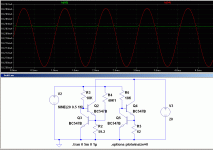
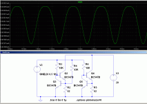
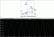
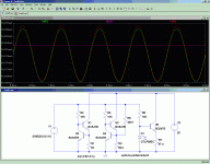
In this example, a 10mA current sink, resistor R4 has been added.
The circuit on the right is the regular CCS used as the reference for comparison.
Without R4, the current variation amounts to 24µA for 1V.
With R4, this variation is only 0.27µA, almost a 100 to 1 improvement.
The value has been fine-tuned for the optimum, and R2 also had to be altered slightly to keep the same current.
I have found the values empirically, it should be possible to derive a formula.
I think it should look something like this:
The ratio of R4 to R2 equals 2(Iout/Ibias)(Vbias/Vbe) (to be checked, at first sight, it seems to work).
It is not necessary to use exact values: the second example uses the nearest standard values, and the delta current has increased to 0.7µA, but it is still a worthwhile gain.
With this method, the PSRR of an amplifier could be improved by 20 to 40dB.
Attachments
I would worry about the range of practical improvement - cancelling Zcb may not be "robust" if the parameter varies with operating point as well as device-to-device
cascodes of various flavors do cost more transistors but can give >100 Meg output Z despite wide device parameter variations
cascodes of various flavors do cost more transistors but can give >100 Meg output Z despite wide device parameter variations
I don't mind adding a resistor, but I don't like the idea of adding one more lytic to anything.I'd just split the bias R and filter or shunt regulate if there's a bias supply noise problem
And a shunt regulator might be a bit of an overkill.
On the other hand, adding this resistor costs practically nothing and does bring a substantial improvement, both dynamically and statically.
I would worry about the range of practical improvement - cancelling Zcb may not be "robust" if the parameter varies with operating point as well as device-to-device
OK, let us do it properly: the formula I guessed in the first post was incorrect (I am becoming lazy with age).
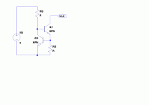
If we look at CCS1, we see that the output current is determined by RE and the Vbe of Q2.
This Vbe is in turn dependent on the bias current, provided by VB and RB.
Because there is a logarithmic relationship between IB and Vbe, this means that this circuit is in fact a (crude) logarithmic converter: Iout is the logarithm of VB.
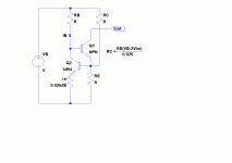
CCS2 shows the situation with the compensating resistor RC. The dynamic emitter resistance of Q2 is shown explicitly, and we can see that for the compensation to occur, the division ratio of RB to re has to be identical to that of RC to RE: this gives the relationship indicated on the schematic.
This is a first order simplified analysis, valid on the conditions variations are small, and bias current is sufficiently high, etc, but it shows the compensation is essentially device-independent.
With the values of the previous example, the formula yields a result of 43K, which is not too far off the mark.
Obviously, the compensation cannot be perfect: a linear compensation will never cancel a logarithmic effect, but for practical purposes, it is useful enough as the example shows.
Attachments
Have you compared your mod to Keantoken's mods/capacitors, particularly with regard to frequency?
Could you provide a pointer to the mods in question?
Extending the principle
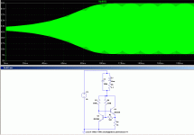
It is possible to extend the compensation principle in order to build a two-terminal current regulator.
The bias resistor is tied to the output, which under normal circumstances would seriously degrade the output impedance.
A compensation resistor can be added to cancel the effect of this resistor.
This time, some gain is needed, and this requires an additional resistor R2.
With the optimum compensation, the current variation for 20V in a 10mA source is 15µA.
Attachments
Further applications
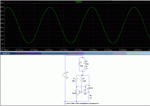
If the circuit is overcompensated, it becomes a negative resistor.
It is the functional equivalent of a lambda diode, but capable of operating at much higher levels.
Like the lambda diode, it can be used as a two terminal oscillator in conjunction with an LC tuned circuit.
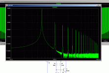
Such an oscillator is capable of providing a very high output level at a low distortion, thanks to its inherent amplitude self-stabilizing property: the negative resistance effect only exists within a limited part of the characteristic.
Attachments
Talking about current sources, I did some simulation work a few months ago on this subject. I looked at active current sources of the type shown above and compared them to the Zener + resistor (Z+R) type used by Leach and Locanthi. I got quite a surprise.
At low frequncies, up to a few KHz, active current sources like the ones above are 8-10db better than the Z+R source (147 vs 156dB line rejection - these numbers are probably a bit optimistic)
Once you get beyond that, the Z+R current source wins
I checked the performance on both positive and negative rail disturbances and got similar results i.e. the Z+R is actually a great performer.
Other than the fact that you need a substantial filter capacitor on the supply feeding the zener, I wonder why the Z+R is not used more widely.
Anyone else have similar experience?
Last edited:
The performance of the LED ccs isn't better than the regular two-transistor CCS, in fact it is slightly worse.Your "normal " CCS is hardly ever used because the referance voltage (current) is the rail, compare your improved CCS to the standard LED (with a cap) voltage referanced CCS and I would bet theres very little improvement.
Using an arbitrarily large decoupling cap, performances of either of the three versions can be made perfect. But if there are degrees in perfection, the LED one will always be slightly worse (and the improved one will always be much better).
Additionally, the improved CCS can be built as a two-terminal version, which means it is polarity-insensitive, and can be used with high voltage N-devices and yet be attached to the positive rail.
Attachments
Obviously not, but they all obey the same laws of semiconductor physics applied to junctions, which is why there is a such a convergence in results: sometimes, depending on processes or materials, an exponent can be 0.85 or 0.82, but basic equations remain the same.Not all leds are the same.
This means there is little to gain by substituting silicon for red or blue LEDs for instance (except for the flashy look, of course).
Real gains are made in the cleverness of design, not exotic components or materials, contrary to widespread belief.
Clever guys as there are some examples on this forum can design better circuits using trash semiconductors of the soviet era than a noob can achieve using the best audiophile components currently available for thousands of $$$$.
Last edited:
- Home
- Amplifiers
- Solid State
- Improved current source/sink
