I've seen the thread on Self's Trimodal amp. That kind of changed into discussions on the merits of regulating rails. Looking back at the Self schematic (more class a than trimodal, I suppose), has anybody tried his class a bias regulator in any projects? Just curious. I thought it was kinda' clever.
Is anybody building/simulating/testing/listening etc. to BJT output class a here? Seems mostly MOSFET that since I've been hanging around. No problem, again, just curious?
Michael
Is anybody building/simulating/testing/listening etc. to BJT output class a here? Seems mostly MOSFET that since I've been hanging around. No problem, again, just curious?
Michael
I'm designing a class A amp based throughout by bjt transistors. This project and the idea to use only bjt-s is also kind of an experiment. I will try some other less explored ideas there, but I'm not willing to discuss them jet. I hope it will get into some material form in about 3 months and then I'm also going to put a web page up....
This is my first posting. I have only registered with this forum in order to correct an apparent misunderstanding.
The bias regulator refered to in the original query is that controlling the output bias current when the amp is operating in Class-A mode. It is a feedback regulator which compares the voltage across the two output emitter resistors with a fixed reference and maintains the Class-A Iq at the appropriate level. If the load current exceeds the Class-A current limit, the Amp will operate in Class-AB mode and the Iq is controlled by a conventional Vbe multiplier. Similarly, if the amp is switched to Class-B mode the conventional Vbe multiplier is used to control Iq.
The LT1166 is designed to control the Iq in a Class-B or Class-AB amp only. It does this by forcing the voltage across the sense (emitter) resistors to +/-20mV. The output stage Iq is therefore equal to 20mV divided by Rsense. For a Class-A Iq of 1.5A (the design value for the Trimodal amp) the sense resistor would require a value of 0.0133 ohms. Not a practical proposition! The LT1166 can only be used for output stage Iqs up to 200mA (with 0.1ohm sense resistors).
I hope this provides some clarification.
Geoff
>>The LT1166 is designed to control the Iq in a Class-B or Class-AB amp only. It does this by forcing the voltage across the sense (emitter) resistors to +/-20mV. The output stage Iq is therefore equal to 20mV divided by Rsense. For a Class-A Iq of 1.5A (the design value for the Trimodal amp) the sense resistor would require a value of 0.0133 ohms. Not a practical proposition! The LT1166 can only be used for output stage Iqs up to 200mA (with 0.1ohm sense resistors).<< A simple resistor voltage divider will set the bias current to any value you want with any value emitter resistors you want.You can set it to 1.5A class A and it will go to class B above this point.A switch may be added to go to full time class B.The LT1166 data sheet shows how to do this.Packaged in an SO8 chip and not needing to be connected to the heatsink in any way allows for easy retrofits on existing equipment.The Self design is ok but the LT1166 is much more versitile.
djk
I'm sorry if I seem pedantic, but the current data sheet for the LT1166 does not show (or refer to) the arrangement you are suggesting. However, that is not to say that it will not work.
The LT1166 may be versatile, but that is of little use here in the UK since none of the usual suppliers stock the device. A discrete component alternative (eg the Doug Self arrangement) can at least be used wherever common type transistors are available.
Geoff
>>Geoff: djk,I'm sorry if I seem pedantic, but the current data sheet for the LT1166 does not show (or refer to) the arrangement you are suggesting. However, that is not to say that it will not work.<< Figure 4 on page 7 shows how to use tapped resistors to change the limit and sense points. This is from the 16 page data and application sheet.It is also on the LinearView CD rom.>> The LT1166 may be versatile, but that is of little use here in the UK since none of the usual suppliers stock the device. A discrete component alternative (eg the Doug Self arrangement) can at least be used wherever common type transistors are available.<< I don't know about UK distribution of LT parts.In the USA one can request samples for free.
djk
Thanks for your reply. Figure 4 does indeed show the use of a tapped sense resistor but this is solely to adjust the limit current. The quiescent current is still controlled directly by the sense resistor (ie the resistance between pins 3 & 8 and pins 3 & 5); in the case of the example in Figure 4 the sense resistance is 1ohm giving an Iq of 20mA. As the lowest practical sense resisor is 0.1ohm, the maximum Iq given by the circuit in Figure 4 is 200mA.
It should be possible to provide a second resistor chain (using higher value resistors) in parallel with the output stage emitter resistor and to tap this second chain at the appropriate point to give an Iq above 200mA. This is the arrangement I thought you were referring to in your previous posting, but this arrangement is not shown in the LT1166 data sheet.
I am not sure how the use of a second resistor chain will affect the accuracy of Iq control since the LT1166 is no longer directly sensing and monitoring the output BJT emitter (or MOSFET drain) current. Unfortunately, I do not have a sample of the device in order to be able to test this arrangement. If anyone has successfully used this device to control a Class-A output stage, perhaps he/she could post the details.
Returning to Michael's original posting and query, yes there are people who have built and are listening to BJT Class-A amps. I'm one of them. My next project will most probably be a Doug Self Trimodal amp so time will tell whether the novel Class-A biasing arrangement is effective, though I've no doubt that it will be.
Geoff
>>This is the arrangement I thought you were referring to in your previous posting, but this arrangement is not shown in the LT1166 data sheet.<< You are absolutely correct. While the exact arrangement I suggested is not shown in figure 4 the idea for tapping either of the sense or limit voltages is raised.While Bob Carver used emitter resistors as low as .05 ohms (M1.5T) values in the range of .1~.5 ohms are more common for BJTs.For the IRFP240/9240 I think .5 ohms would be the minimum I would use.I am building a variation of this patent for biasing an IRFP240/9240 pair in a common source set up. http://www.delphion.com/cgi-bin/viewpat.cmd/US04570129__
Thanks. I'm glad we're in agreement at last! A diagram could have saved us a lot of time and typing but I've not yet found a way of pasting one into a message.
ouch - been here a bit to have missed that - you need to click "go advanced" button below the reply text box, then scroll down to "Attach Files">"manage attachments"
then you can upload image(s) from your computer to diyAudio so you don't need your own website or photo/image hosting server
My class A
Hi Mlloyd1,
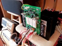
I have recently designed and built a class A amp as part of a "challenge"")
It does not require traditional bias regulator.
Here is the initial post:
My class A pictures and specs
Here are the docs:
My class A gerbers, etc.
Let me know if you have some questions
Cheers,
Valery
I've seen the thread on Self's Trimodal amp. That kind of changed into discussions on the merits of regulating rails. Looking back at the Self schematic (more class a than trimodal, I suppose), has anybody tried his class a bias regulator in any projects? Just curious. I thought it was kinda' clever.
Is anybody building/simulating/testing/listening etc. to BJT output class a here? Seems mostly MOSFET that since I've been hanging around. No problem, again, just curious?
Michael
Hi Mlloyd1,
I have recently designed and built a class A amp as part of a "challenge"
It does not require traditional bias regulator.
Here is the initial post:
My class A pictures and specs
Here are the docs:
My class A gerbers, etc.
Let me know if you have some questions
Cheers,
Valery
Attachments
wow valery, you've been working on that project for long time while since it's taken 13 years for a response ...
just kidding.
thanks, i've looked at a number of your project posts, so i'll add this one to the list
mlloyd1
Hahah
Sometimes I'm a little bit slow 
The bias regulator refered to in the original query is that controlling the output bias current when the amp is operating in Class-A mode. It is a feedback regulator which compares the voltage across the two output emitter resistors with a fixed reference and maintains the Class-A Iq at the appropriate level. If the load current exceeds the Class-A current limit, the Amp will operate in Class-AB mode and the Iq is controlled by a conventional Vbe multiplier. Similarly, if the amp is switched to Class-B mode the conventional Vbe multiplier is used to control Iq.
I hope this provides some clarification.
Geoff
Hi,
Not really. I quizzed D.Self on this very point and got the rather
disappointing reply "it's too complicated to explain". It isn't,
the class A controller can't handle class A entering class AB.
I asked what happens if class A mode enters class B.
That the conventional Vbe multiplier takes over is beyond me.
Even if it does, that is going to be relatively very non-linear.
Seems to me if you expect class AB to occur your best off
with a conventional Vbe multiplier to set the class A current.
Very much like a Class A kit I've seen that does exactly that,
in all other respects it is very near identical to the Trimodal.
Silicon Chip magazine in Australia I recall, around 2007.
The articles appears to be a pain to find for some reason.
(Seems due to Silicon chip having a new website).
This kit :
http://www.altronics.com.au/p/k5125-20w-class-a-amplifier-full-kit/
rgds, sreten.
Last edited:
Thanks sreten, I've been wondering how it could possibly operate in Class B. I wondered if perhaps the 47uF cap across the bias controller could carry the signal faster than the (as Self said, relatively 'slow') controller could suppress it...
I built that SC amplifier and was astounded by it when I was 21, but I shorted it and have been building speakers since. Back to electronics for now and I'll resurrect that amp ASAP... I have the boards by my desk now, just need to troubleshoot. I found it a superbly easy schematic to understand, and it's perfect for where I am at the moment.
I built that SC amplifier and was astounded by it when I was 21, but I shorted it and have been building speakers since. Back to electronics for now and I'll resurrect that amp ASAP... I have the boards by my desk now, just need to troubleshoot. I found it a superbly easy schematic to understand, and it's perfect for where I am at the moment.
- Status
- This old topic is closed. If you want to reopen this topic, contact a moderator using the "Report Post" button.
- Home
- Amplifiers
- Solid State
- Anybody played with Self Class A bias regulator?