I had to change some of elements (R2, R11, Cny 17-2) and to correct wiring form transformer. I've do this, but this amp still not working. There is no voltage on the triac (MT2). The wires from the transformer green and white, green and brown, blue and white, blue and brown are separated (or burned?), is that OK? I don't know for what are wires white and brown...
I had to change some of elements (R2, R11, Cny 17-2) and to correct wiring form transformer. I've do this, but this amp still not working. There is no voltage on the triac (MT2). The wires from the transformer green and white, green and brown, blue and white, blue and brown are separated (or burned?), is that OK? I don't know for what are wires white and brown...
usually Carvers from PM1.5 family have a transformer with 4 wires: green/blue/brown/white for the dual primary and 7 wires: yellow/orange/red/black/red/orange/yellow for secondary coil.
there are 2 primary coils wich is to be connected in parallel for 120V. green with brown and blue with white.
green and brown conected to toroidal choque, after the control pcb, and white and blue conected on MT2 of triac.
If your wires are of two colors each, simply measure the continuity between wires, to determine what is each half of the primary.
if you need more help, send me (by PM) a copy of service manual, for cross comparision with my personal notes about that transformers.
Hope it help.
Marcos
You're right, becouse the brown and white wires are shorted in 240V, and paralleled with blue and white in 120V version. So my next question is: how I can check if triac (alternistor) q2025p is not burned? Now, on gate is 240V, on MT1 is 245V and on MT2 is 0V... so there is no voltage on primary coil.
I've repaired the regulator board. The amplifier starts. I have problem with regulation of voltage (placed on amplifier board). I've replaced 4558d (U1) but with no effect. Voltage on the U1(1) is 7V DC -this is to much I think. With regulation cutted off: secondary voltage is 56V DC and this is ok. But when I plug in regulation from the amp board to regulator board, the secondary voltage is 120V and transformer is making great noise. What i should check? RP1 should have max resistance, or min?
When I disconnect U1 from optocoupler there was 60VDC on rail.
I have to:
1. correct wiring from transformer to regulator board
2. change OC1 from CNY 17-4 to CNY 17-2
3. change R11 from 52 ohm (burned) to 18 ohm
4. change R2 (62K), it was burned
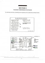
Below I present a picture of corect wiring (in service manual there was mistake for 240V wiring). The wiring form transformer to regulator board should be like in pm-600.
potentiometer RP1 should have minimal resistance.
I have to:
1. correct wiring from transformer to regulator board
2. change OC1 from CNY 17-4 to CNY 17-2
3. change R11 from 52 ohm (burned) to 18 ohm
4. change R2 (62K), it was burned
Below I present a picture of corect wiring (in service manual there was mistake for 240V wiring). The wiring form transformer to regulator board should be like in pm-600.
potentiometer RP1 should have minimal resistance.
Attachments
Last edited:
Ok. I know what happens. My amplifier have transformer from PM-1201 or PM-1.5. I don't know how i can bring it to life. What i should change in this amplifier? so it will can work with this transformer. I have the rail voltage but transformer make great noise... The rail voltage is 124V DC like in PM 1.5
Check www.thecarversite.com for repair questions. They are Carver fans and more than eager to help on this.
pgrad: you a can't really use the transformer from a PM1.5 / PM1200 in a PM350. The rail voltage will be too high, so the output stage will try to deliver too much power.
You could reduce RP1, but the transformer would end up hardly firing, i.e. you'd probably get a lot of buzz / interference.
You'd do better to put the amp away, and set up some searches on ebay in case a unit comes up.
You could reduce RP1, but the transformer would end up hardly firing, i.e. you'd probably get a lot of buzz / interference.
You'd do better to put the amp away, and set up some searches on ebay in case a unit comes up.
I need Service Manual for Carver 350 Mariner 2003
My Email address is:
krhart@cisco.com
I have the whole Service Manual, PM me with your email.
Craig
My Email address is:
krhart@cisco.com
- Status
- This old topic is closed. If you want to reopen this topic, contact a moderator using the "Report Post" button.
- Home
- Amplifiers
- Solid State
- Anyone with Carver pm-350 diagram?