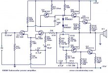
Besides, C3 should be at least 100uF if you expect a decent bass reproduction from that amp. C2 can also be 10 times higher value and you should buy a lot of Q1/Q2 transistors and plan for sockets on the PCB for them (in order to match them in situ, to obtain acceptable DC offset at amp's output - or insert the 47R pot between their emitters to adjust the DC offset manually). D1 and D2 should be mounted to touch the main heatsink and R9/R10 should be easily changeable (or use a pot instead of them) to achieve about 50-100mA of Iq through Q5 and Q7.
It's far from perfect amplifier but it will do as a mediocre subwoofer or guitar amp...
It's far from perfect amplifier but it will do as a mediocre subwoofer or guitar amp...
Besides, C3 should be at least 100uF if you expect a decent bass reproduction from that amp. C2 can also be 10 times higher value and you should buy a lot of Q1/Q2 transistors and plan for sockets on the PCB for them (in order to match them in situ, to obtain acceptable DC offset at amp's output - or insert the 47R pot between their emitters to adjust the DC offset manually). D1 and D2 should be mounted to touch the main heatsink and R9/R10 should be easily changeable (or use a pot instead of them) to achieve about 50-100mA of Iq through Q5 and Q7.
It's far from perfect amplifier but it will do as a mediocre subwoofer or guitar amp...
I have tested this circuit as you told i changed c2 and c3 sounds nice but Iq of Q7 is little higher than Q5 how can i adjust both of them equal Iq
Hi,
Iq of Q5 & Q7 depend on the voltage across the base emitter resistors (R15 & R13) and on the voltage across the emitter resistors (R16 & R14) and on the Vbe of the transistors.
Whereby Vbe+Vre = Vrbe
The resistors must be matched if you want to use them to tell you the currents that are flowing.
The collector current coming out of Q6 must equal the emitter current coming out of Q4.
Look up Baxandall & JLH to see the loading you must add to your drivers to make them perform more equally. You need an extra resistor + capacitor + diode.
The only thing left that can affect the Iq is the Vbe of the two output transistors. These must be matched at the Iq you intend to use.
Last edited:
- Status
- This old topic is closed. If you want to reopen this topic, contact a moderator using the "Report Post" button.