JFET has a different sort of distortion than BJT.
Most poweramps have BJT input + Error correction.
And even those poweramps having JFET inputs
has got so much gain and negative feedback,
that they should not sound at all or sound just like BJT.
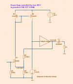
This idea of mine uses only 1 JFET to amplifiy and take care of feedback.
It will have some distortion, but of the type of dist that JFET has.
See diagram.
It is a very simplified presentation of my idea.
The signal comes across R3.
You need no input cap, but we usually attach one anyway.
2N4416 JFET was chosen because of VGS.
2SK170 is not very good, because here we need VGS 1-2 Volt for producing some milliAmperes.
On top is current mirror.
That mirror will not change or amplifiy. Just mirror.
On the bottom is corresponding CCS, current source,
to balance current coming from mirror.
This stage drives the output stage follower.
The feedback and gain is handled by R2/R4.
And feedback is taken to the JFET Source.
What is important is to add a good output stage.
One JFET (or other small signal device) will give more distortion
the heavier the load is.
So, to give suitable light load here I would say we need a
Triple Darlington or similar.
With very high input impdance.
I have a couple good working protypes in SPICE.
Where distortion is at very respectable level.
I will post one.
And, yes!
It gives what I was after: mostly 2nd order distortion.
THE FET SOUND is here ...
Most poweramps have BJT input + Error correction.
And even those poweramps having JFET inputs
has got so much gain and negative feedback,
that they should not sound at all or sound just like BJT.
This idea of mine uses only 1 JFET to amplifiy and take care of feedback.
It will have some distortion, but of the type of dist that JFET has.
See diagram.
It is a very simplified presentation of my idea.
The signal comes across R3.
You need no input cap, but we usually attach one anyway.
2N4416 JFET was chosen because of VGS.
2SK170 is not very good, because here we need VGS 1-2 Volt for producing some milliAmperes.
On top is current mirror.
That mirror will not change or amplifiy. Just mirror.
On the bottom is corresponding CCS, current source,
to balance current coming from mirror.
This stage drives the output stage follower.
The feedback and gain is handled by R2/R4.
And feedback is taken to the JFET Source.
What is important is to add a good output stage.
One JFET (or other small signal device) will give more distortion
the heavier the load is.
So, to give suitable light load here I would say we need a
Triple Darlington or similar.
With very high input impdance.
I have a couple good working protypes in SPICE.
Where distortion is at very respectable level.
I will post one.
And, yes!
It gives what I was after: mostly 2nd order distortion.
THE FET SOUND is here ...
Attachments
JFET has a different sort of distortion than BJT.
Most poweramps have BJT input + Error correction.
And even those poweramps having JFET inputs
has got so much gain and negative feedback,
that they should not sound at all or sound just like BJT.
This idea of mine uses only 1 JFET to amplifiy and take care of feedback.
It will have some distortion, but of the type of dist that JFET has.
See diagram.
It is a very simplified presentation of my idea.
The signal comes across R3.
You need no input cap, but we usually attach one anyway.
2N4416 JFET was chosen because of VGS.
2SK170 is not very good, because here we need VGS 1-2 Volt for producing some milliAmperes.
On top is current mirror.
That mirror will not change or amplifiy. Just mirror.
On the bottom is corresponding CCS, current source,
to balance current coming from mirror.
This stage drives the output stage follower.
The feedback and gain is handled by R2/R4.
And feedback is taken to the JFET Source.
What is important is to add a good output stage.
One JFET (or other small signal device) will give more distortion
the heavier the load is.
So, to give suitable light load here I would say we need a
Triple Darlington or similar.
With very high input impdance.
I have a couple good working protypes in SPICE.
Where distortion is at very respectable level.
I will post one.
And, yes!
It gives what I was after: mostly 2nd order distortion.
THE FET SOUND is here ...
Link p12 has FETs on it.
Distortion depends a bit on the accuracy of the SPICE model which may not match reality for that degree of analysis - but I do like FETs.
If you really just want 2nd and very little else, you need a triode front end like a nice 6N2P or 12AX7
")
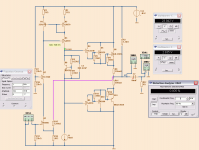
JFET with triple darlington
Triple darlington output works the best.
- Class AB
- Max 25 Watt into 8 OHM
- Less than 0.020 % THD at 25 Watt
- It is fast, 2 MHz -3dB at gain >20
Second Image shows 25 Watt into 8 ohm
Triple darlington output works the best.
- Class AB
- Max 25 Watt into 8 OHM
- Less than 0.020 % THD at 25 Watt
- It is fast, 2 MHz -3dB at gain >20
Second Image shows 25 Watt into 8 ohm
Attachments
Last edited:
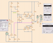
A little thinking...on your concept...Sure it'll sound good.. distortion is app -85 dB second order...then dropping to app -100 dB third and even lover 4.th...
Dual rail lateral FET output..here with 600 mA..app 30 W dissipation each...a little hot maybe..
DC component:0.00494159
Harmonic Frequency Fourier Normalized Phase Normalized
Number [Hz] Component Component [degree] Phase [deg]
1 1.000e+03 7.672e+00 1.000e+00 -0.18° 0.00°
2 2.000e+03 4.651e-04 6.062e-05 85.67° 85.85°
3 3.000e+03 4.593e-05 5.987e-06 49.85° 50.03°
4 4.000e+03 1.180e-06 1.537e-07 -117.73° -117.54°
5 5.000e+03 3.060e-07 3.988e-08 -80.47° -80.28°
6 6.000e+03 4.605e-08 6.002e-09 51.90° 52.09°
7 7.000e+03 5.001e-08 6.519e-09 -2.38° -2.19°
8 8.000e+03 3.390e-08 4.418e-09 -46.01° -45.83°
9 9.000e+03 7.551e-08 9.842e-09 167.27° 167.46°
Total Harmonic Distortion: 0.006091%
Attachments
Last edited:
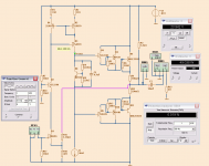
if you talk about my take on the nice Lineup concept..
Then I think it will perform quite well.. when driven harder distortion increases but maintains the same kind of distribution...with predominantly 2. order..
The lateral fets slide gently into class B operation..and the feedback currents are smooth with no trace of switching spikes...
I believe that it will be a good music performer..
Harmonic Frequency Fourier Normalized Phase Normalized
Number [Hz] Component Component [degree] Phase [deg]
1 1.000e+03 2.301e+01 1.000e+00 -0.19° 0.00°
2 2.000e+03 4.672e-03 2.030e-04 83.92° 84.12°
3 3.000e+03 6.458e-04 2.806e-05 -26.08° -25.88°
4 4.000e+03 1.800e-04 7.823e-06 179.05° 179.24°
5 5.000e+03 3.477e-04 1.511e-05 80.23° 80.43°
6 6.000e+03 1.901e-04 8.262e-06 171.35° 171.54°
7 7.000e+03 3.969e-04 1.725e-05 81.88° 82.07°
8 8.000e+03 7.447e-05 3.236e-06 178.11° 178.30°
9 9.000e+03 1.487e-04 6.460e-06 82.14° 82.34°
Total Harmonic Distortion: 0.020665%
Attachments
CopperTop.....What is the point..???
This is not by a long shot the most well specified amplifier...but the pure simplicity of the circuit and the nature of distortion does hold some promise.... Think lineup has found a very good way to use the Jfet..to keep it simple and at the same time keep it scalable..and flexible.. gain can be adjusted to fit the needs...here as a Power amp...but by inserting a different buffer also as a nice preamp..with really good specs for such a simple circuit.. could also pose as a nice I-V converter for DAC's.
To me a good circuit building block with plenty of applications...and variations
app same distortion as the lateral fet version....think the feedback injection below the Jfet is the decisive factor...
I have decreased feed back a little and increased gain to 30 dB....bandwith is app 300 Khz at -3 dB
I have worked a little more on the concept and fitted a non switching output stage, separate supplies with +-60 V for the front end and +- 50V for the output stage....I plan to build it...thanks
I have decreased feed back a little and increased gain to 30 dB....bandwith is app 300 Khz at -3 dB
I have worked a little more on the concept and fitted a non switching output stage, separate supplies with +-60 V for the front end and +- 50V for the output stage....I plan to build it...thanks
It will distort when too high voltage input.Clip.How does this amp perform if you overdrive it?
For 4 ohm it looks good.
- Status
- This old topic is closed. If you want to reopen this topic, contact a moderator using the "Report Post" button.
- Home
- Amplifiers
- Solid State
- One JFET poweramp looking for THE FET SOUND