Is a perfectly simetrical amplifier, this will be my prototype.
Power supply will be +/- 95 Vdc, I have tested at +/- 112 Vcc (idle), dropping till +/- 92Vdc (at full power on dummy load).
I estimate around 500Watts on 8 ohms and 800Watts at 4 ohms.
Protection will activate, under 2,66 ohms load, killing the differential INPUT stage.
Some testing movies on dummy load on sinewave:
YouTube - 1 Prezentare+Reglaj Bias.MOV
YouTube - 2 Bias Reglat.MOV
YouTube - 3 30Hz-200Hz On 8 Ohm.MOV
YouTube - 4 200Hz-60Khz On 8 Ohm.MOV
YouTube - 5 Explicatii Dupa Test.MOV
YouTube - 6 100Hz-15hz + Scurt.MOV
YouTube - 7 30Hz-20Khz On 4 Ohm.MOV
YouTube - 8 Idei Finale.MOV
Testing on musc signal:
Part 1 music test
YouTube - Part 1 Music Test.MOV
Part 2 music test
YouTube - Part 2 Music Test.MOV
Part 3 music test
YouTube - Part 3 Music Test.MOV
Maximum output power on 8 and 4 ohms
YouTube - Maximum Output Power On 8 And 4 Ohms Speakers..MOV
1 W 8 ohm linearity
YouTube - 1W- 8 Ohms Linearity.MOV
Some amusement tests:
YouTube - Film 1.MOV
YouTube - Film 2.MOV
YouTube - Film 3.MOV
Megashooting...
YouTube - Film 4 Dif.MOV
YouTube - Film 5.MOV
YouTube - Film 6.MOV
YouTube - Film 7.MOV
And some dreptunghiular and triunghiular signals testing:
YouTube - Dreptunghhiular 1.MOV
YouTube - Dreptunghhiular 2
YouTube - Dreptunghhiular 3.MOV
Please have patience and watch all movies from start till the end.
Free for comments, opinions, etc.
Please don't ask fost schematics, that's my prototype.
Thanks for understanding.
Power supply will be +/- 95 Vdc, I have tested at +/- 112 Vcc (idle), dropping till +/- 92Vdc (at full power on dummy load).
I estimate around 500Watts on 8 ohms and 800Watts at 4 ohms.
Protection will activate, under 2,66 ohms load, killing the differential INPUT stage.
An externally hosted image should be here but it was not working when we last tested it.
An externally hosted image should be here but it was not working when we last tested it.
An externally hosted image should be here but it was not working when we last tested it.
An externally hosted image should be here but it was not working when we last tested it.
An externally hosted image should be here but it was not working when we last tested it.
An externally hosted image should be here but it was not working when we last tested it.
An externally hosted image should be here but it was not working when we last tested it.
An externally hosted image should be here but it was not working when we last tested it.
An externally hosted image should be here but it was not working when we last tested it.
An externally hosted image should be here but it was not working when we last tested it.
An externally hosted image should be here but it was not working when we last tested it.
An externally hosted image should be here but it was not working when we last tested it.
Some testing movies on dummy load on sinewave:
YouTube - 1 Prezentare+Reglaj Bias.MOV
YouTube - 2 Bias Reglat.MOV
YouTube - 3 30Hz-200Hz On 8 Ohm.MOV
YouTube - 4 200Hz-60Khz On 8 Ohm.MOV
YouTube - 5 Explicatii Dupa Test.MOV
YouTube - 6 100Hz-15hz + Scurt.MOV
YouTube - 7 30Hz-20Khz On 4 Ohm.MOV
YouTube - 8 Idei Finale.MOV
Testing on musc signal:
Part 1 music test
YouTube - Part 1 Music Test.MOV
Part 2 music test
YouTube - Part 2 Music Test.MOV
Part 3 music test
YouTube - Part 3 Music Test.MOV
Maximum output power on 8 and 4 ohms
YouTube - Maximum Output Power On 8 And 4 Ohms Speakers..MOV
1 W 8 ohm linearity
YouTube - 1W- 8 Ohms Linearity.MOV
Some amusement tests:
YouTube - Film 1.MOV
YouTube - Film 2.MOV
YouTube - Film 3.MOV
Megashooting...
YouTube - Film 4 Dif.MOV
YouTube - Film 5.MOV
YouTube - Film 6.MOV
YouTube - Film 7.MOV
And some dreptunghiular and triunghiular signals testing:
YouTube - Dreptunghhiular 1.MOV
YouTube - Dreptunghhiular 2
YouTube - Dreptunghhiular 3.MOV
Please have patience and watch all movies from start till the end.
Free for comments, opinions, etc.
Please don't ask fost schematics, that's my prototype.
Thanks for understanding.
500W into 8r0 from loaded supply rails of +-92Vdc is a good result. You are losing just 2.56V from supply to output (89.44Vpk).
The 800W into 4r0 result is pretty poor by comparison. It is 1dBV down on the 8r0 result and shows a voltage loss that increases from a good 2.56V to a very poor 12Vlost.
Your protection is badly designed if it damages the front end when triggered.
Check what the VAS stage currents are when the protection is active (triggered). The VAS must be self protecting if the output can be clipped and/or protected.
Are catch diodes fitted across the caps and output rail to limit the back emf from the moving driver VC and capacitors/inductors?
AndrewT, please have patience to watch ALL movies entirely ,and we'll speak after.
Using 4 ohm instead 8 ohm for dummy load, the power supply is sagged and dropes more significantly!
I never saw an amplifier AB class wich his power in 4 ohms will be doubled comparing to 8 ohms power.
Also, outputs power that I said (500 and 800 watts) are relative.
You will see that after watching all movies entirely.
The protection works flawless, the amplifier will have separate section for limmiter and mutting.
Last edited:
Hi,I never saw an amplifier AB class which his power in 4 ohms will be doubled comparing to 8 ohms power.
neither have I.
Cordell suggests a good amp will give 180% into a half resistance load.
I set a slightly lesser standard than his.
I have built many amps that are -0.4dBV to -0.6dBV down into halved load resistance.
I would reject an implementation that was -1dBV down into 4r0 ref. 8r0.
I will repeat, somewhat re-phrased, what I said earlier: your reported 8r0 power performance is good. Your reported 4ohm power performance is far from good.
I do not need to watch movies to read this.
Last edited:
well ...that looks very promessing ... i will not go to calculations or thepry but for starts the pcb is very badly designed ...way too many parallel lines and proximity between traces will cause some trouble ...
respecting your statement about the circuit but still it would be interesting to see
kind regards sakis
respecting your statement about the circuit but still it would be interesting to see
kind regards sakis
Could you post a schematic of this amplifier please. Looks like a very professional pcb you have made. Nice work.
Tad
Tad
Symetrical input stage (mirrored) receive 1mA current, from precision constant current generator, thermally compensated.
Watching Makie M1400 schematics, mine amplifier is more more simplistic, and does't look the same.
Sorry, schematics will not be posted because is mine prototype.
PCB is JUST for testing purpose, professional PCB will arive in 2-3 weeks.
So on this simple PCB works like that, in a pro PCB will work minimally the same!
I'm satisfied with the results of it.
Last edited:
 Non-English post removed. Please see the forum rules. One's English doesn't have to be great, but English IS the official language of this forum due to wide international participation.
SY, I understand the forum rules but you must to make an exception!
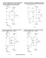
@Dj Leco, congratulations for the achievement. An yes, your amplifier is more simplistic that M1400. Eventually, you use a protection diagram transistors like that (see post no.10, fig.4):
circuit de protectie la scurtcircuit pe iesire la amplificatoarlee audio - Comunitatea Tehnium Azi
?????
Nice day.
Mine protection Kill entire input stage, not pilot transistors!
That means at accidental shortcircuit on outout(as you can see in some movies posted), will shot down differential input stage.
Also second protection will activate with some delay,(mutting) the general input level, untill overload dissapear.
Also will be thermally protection with bimetal or LM350 circuit.
But all these in other module separately.
Thanks to all for encouraging, my project.😉
Excuse some mismatch spelling, too!🙄
donpetru, I must be logged on that forum, please pick up that schematic, upload it on tinypic and follow it's link, here, thank you!
Last edited:
Could you post a schematic of this amplifier please. Looks like a very professional pcb you have made. Nice work.
Tad
a square and symmetric pcb doesnt solve the problems ..it is very well known that in audio applications square corners and parallel lines will not perform properly ...proximity is also an issue ...
other than that yeap !!! it looks in order very square and very symmetric of course this doesnt mean that will work properly
regards sakis
Protection will activate,............killing the differential INPUT stage.
please explain why killing = flawless.The protection works flawless, the amplifier will have separate section for limiter and muting.
Last edited:
I think he means killing the bias in the input stage. Not the parts. 😀 Doing that wouldn't be very productive.
So have you built an amplifier that does 500W into 8 ohms and 900W into 4 ohms like you suggest is needed to be "good"? It requires "a little" more extra bulk than getting so close to doubling in a 100W / 8 ohm amplifier...
So have you built an amplifier that does 500W into 8 ohms and 900W into 4 ohms like you suggest is needed to be "good"? It requires "a little" more extra bulk than getting so close to doubling in a 100W / 8 ohm amplifier...
In my case will shot down the differential outputs before go further in schematic.
Hope this explains better:
donpetru, the pcb wasn't made by me, it was made by a friend of mine on CNC machine.
megajocke, as I said, the 500 and 800 watts power are estimative, I will give a test today to observe maximum power on 8 ohms speaker and another 8 ohm speaker, added parallel(4 ohms), also without speaker(no load) trying to calculate the damping factor(aproximately) too.
Keep close, Romanian time is 3:21 AM, and till 17:10 is "sleeping time" for my neighbours...
Hope this explains better:
An externally hosted image should be here but it was not working when we last tested it.
donpetru, the pcb wasn't made by me, it was made by a friend of mine on CNC machine.
megajocke, as I said, the 500 and 800 watts power are estimative, I will give a test today to observe maximum power on 8 ohms speaker and another 8 ohm speaker, added parallel(4 ohms), also without speaker(no load) trying to calculate the damping factor(aproximately) too.
Keep close, Romanian time is 3:21 AM, and till 17:10 is "sleeping time" for my neighbours...
Last edited:
don't use a reactive load.as I said, the 500 and 800 watts power are estimative, I will give a test today to observe maximum power on 8 ohms speaker and another 8 ohm speaker, added parallel(4 ohms), also without speaker(no load) to try to calculate the damping factor(aproximately) too.
Use a truly resistive test load.
I use a large bank of 5W wirewounds to produce 100W and 200W loads of 8r0+-0.5%
Hi, as a mental exercise and to understand the consequences of protection, take a moment in time when the output is at -30V with +-35Vsupply rails and connect the output to ground with a 1r0 resistor.In my case will shot down the differential outputs before go further in schematic.
Hope this explains better:
An externally hosted image should be here but it was not working when we last tested it.
Hold this snapshot and put in all your voltages and currents and see what the protection transistor has done to load up the VAS. Does this condition damage the VAS? Will the active (triggered) protection transistor and/or the damaged VAS cause consequential damage to the input stage?
Last edited:
don't use a reactive load.
Use a truly resistive test load.
I use a large bank of 5W wirewounds to produce 100W and 200W loads of 8r0+-0.5%
I will make into speakers and into dummy load too, I have 2 pieces of 4 ohms/500Watts power, with low thermal derate, and low inductance too.
That means you don't saw it, because you don't have watched movies in mine first post...
Hi, as a mental exercise and to understand the consequences of protection, take a moment in time when the output is at -30V with +-35Vsupply rails and connect the output to ground with a 1r0 resistor.
Hold this snapshot and put in all your volates and currents and see what the protection transistor has done to load up the VAS. Does this condition damage the VAS?
Whai is VAS?.
In my movies, IF ALL OF YOU, will have PATIENCE to watch it all from start till end, you will see SHORTCIRCUITS, DIRECTLY TO OUTPUT,AND UNDER 2 OHMS LOADING TOO with suplimentar dummy loading,during tests...
Protection works flawless, but must watch movies and see...
Last edited:
I think it was better if implemented protection from Mackie 1400 input stage. But who knows, maybe the next version of the amplifier!
The VAS is the transadmittance stage. At this stage, a word to say on performance amplifier it is determined solely by the Miller capacitor (called C_dom). All the voltage gain is provided by the VAS stage, which makes for easy compensation. The local NFB (negative feedback) working on the VAS through C_dom has an extremely valuable linearising effect.
Any amplifier operates in two regions: the LF, where open-loop gain is substantially constant, and HF, above the dominant-pole breakpoint, where the gain is decreasing. This regions must be controlled carefully by choosing proper values of capacitors and value NFB diagram audio amplifier. In the HF region, things are distinctly more difficult as regards distortion.
Nice day everyone.
Last edited:
- Status
- Not open for further replies.
- Home
- Amplifiers
- Solid State
- Class AB amp made by me.