Mission Cambridge amplifier
Hi Klaus,
I am trying to reinstate the amplifier.
The burnt resistors look like old Alain Bradley 1/2 watt.
I am now sourcing the resistors.
I don't know the condition of the driver transistors but following that
the resistors burnt I suspect that there is / are faulty transistor/transistors.
The D666 ST transistors are available locally but the B646 are not.
They have chinese replacements 647.
Will try to secure the B646.
But again will first try with the resistors .
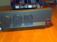
Klaus, please note that the amplifier model is Mission Cambridge (not 778 or any other).
BTW the importer who sold this amplifier to me claimed that it sounded better than both the Cyrus 1 and Cyrus 2 .
It was somewhere at the level of Musical Fidelity A1 (possibly slightly below).
Unfortunately Mission do not keep nor any spare parts nor the curcuit diagrams of these early models amplifiers from the time they were one company with the today Cyrus .
Best regards,
Aleko
Hi Klaus,
I am trying to reinstate the amplifier.
The burnt resistors look like old Alain Bradley 1/2 watt.
I am now sourcing the resistors.
I don't know the condition of the driver transistors but following that
the resistors burnt I suspect that there is / are faulty transistor/transistors.
The D666 ST transistors are available locally but the B646 are not.
They have chinese replacements 647.
Will try to secure the B646.
But again will first try with the resistors .
Klaus, please note that the amplifier model is Mission Cambridge (not 778 or any other).
BTW the importer who sold this amplifier to me claimed that it sounded better than both the Cyrus 1 and Cyrus 2 .
It was somewhere at the level of Musical Fidelity A1 (possibly slightly below).
Unfortunately Mission do not keep nor any spare parts nor the curcuit diagrams of these early models amplifiers from the time they were one company with the today Cyrus .
Best regards,
Aleko
Last edited:
Aleko,
can you please take some photographs from your amp from all sides outside and inside? Close-ups from the pcb and the broken parts will be very good for me trying to help you a bit more specific.
As you may have read in some other Cyrus based threads here, there were many different series or incarnations of these amps. Before that all Mission amps had some number (like other mission products starting with 7, which the constructor Henry Azima may have considered a lucky number for his enterprise). A "Mission Cambridge" titled amp is unknown to me. So your amp probably is a very rare item - I will do my best to help you.
In my old comparison chart book from 1992 the 2SB646 compares to the 2SA1124, the 2SB647 is comparable but with much more power (0.05A to 1A), equivalent to the 2SB1212.
The equivalent to the 2SD666 is the 2SC2632, again the stronger comparable one is 2SD667 (or 2SD1812).
This is not verfied by web reseach, and does not say anything about a possible change in sound.
The equivalent to the 2SD666 is the 2SC2632, again the stronger comparable one is 2SD667 (or 2SD1812).
This is not verfied by web reseach, and does not say anything about a possible change in sound.
Mission Power Amplifier Module 1
Hi Klaus,
Thank you for providing information about the replacements of the 2SB646 and 2SBD666.
Unfortuntely I have not been successful at repairing the power amplifier module so far.
In fact I replaced all of the 220ohm and 390 ohm resistors with tantalum film Audio Note 1/2 watt.
I also replaced one faulty 2SBB646 which short circuited inside.
It worked for a few hours and then something else happened.
Now it is that as soon as you turn it on 2 of the (new) resistors get very hot and start to smell very quickly.
I immediately swich it off so that they do not get burnt.
The traces got damaged in some areas when I did the resoldering of the new components.
I managed to find 2SB646 - 3 and the 2SA1124 and 2SD666 are available.
I seem to have already got lost due to unknown damaged either traces or transistors.
Best regards,
Aleko
Hi Aleko,
again, please take some close-up photographs of your amp - I have no schematics to refer to and very little information about your circuit's design. It is very difficult to help you here.
When a resistor gets very hot, there is most likely another semiconductor failure nearby. I suppose the resistors you mentioned are part of the output stage (a triple darlington??) and so maybe some or all of the driver transistors are also faulty. What types does your amp use? But the fact that the amp broke again after some time can have many reasons.
Mission Cambridge
Hi Klaus,
Will take up the photos in due course and post them here.
'Triple Darlington ' - you said it .
I think you are right .
At this point after I have replaced all transistors and 12 resistors the repaired channel already works but has some +0.2V offset.
The traces are extensively damaged so some of the elements are connected one to another directly .
It looks awful from the bottom of the board.
Strangely enough the offset went to -0.2V earlier today.
What is it doing, fluctuating ?
There are one 2SA872 on the negative side and one 2SC1775 transistors on the positive side which seem to feed the 4 NPN 2SD666 and the 4 PNP 2SB646 respectively .
When I replaced the 2SC1775 with the another one the offset changed from significantly from 0.5V to 0.2 V.
Are these 872 and 1775 complementary and if so do I need to match them?
Will post photos tomorrow.
regards,
Aleko
there is nothing found in the net about your amp - that is why I doubted that the "real" name of the amp must also be something more specific than "Mission Cambridge".
If only a (complimentary) pair of 2SC1775 and 2SA872 are driving the output transistors (parallel?) it is not a triple darlington, but these transistors are low power (and should probably really be matched). So I am even more curious about your photos!
If only a (complimentary) pair of 2SC1775 and 2SA872 are driving the output transistors (parallel?) it is not a triple darlington, but these transistors are low power (and should probably really be matched). So I am even more curious about your photos!
Mission Cambridge - power amp module
Hi ,
I am posting 3 photos.
I think that what you say is correct.
There are 2 complementary 2SC1775 and 2SA872 at the input .
they are connected in a circuit starting with the power supply rail through 1 ohm resistor then one C1775 connected through the offset regulator to the input A872 (the other leg through a 74 ohm resistor).
The other side is quite similar with the only difference that it starts with the negative power rail through the 1 ohm resistor to A872 which is then connected to the input C1775.
So it has 2 C1775 and 2 A872 in this circuit .
What is this - maybe the input phase splitter ?
I noticed that the offset is very sensitive on the C1775 and A872 .
By replacement of the C1775 connected to the power rail through the 1 ohm resistor it moved from 0.2 V to 0.5 V .
Then another change and it is now 0.8 V.
I have replaced the 2SD666 with new ones (reportedly Hitachi)
and the 2SB646 with 2SA1124 reportedly Matsushita.
I also noticed that a random change of one of the say 2D666 also changes the offset .
The resistors seem to be good throughout (I mean the originals ones that remained) - they measure equal on both sides.
I don't know how to match transistors and the random replacements that I do always happen to keep the offset above zero .
I never had it below zero .
please note that the 4 100 mF 100V capacitors have been removed on photo 1 .
Best regards,
Aleko Markov
Attachments

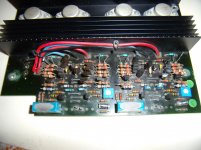
without further study of your amps images:
It is definitely a Mission 778 amp, the predecessor of the mission cyrus amps. Stan Curtis designed the Mission 776/777 preamp and amp - I think the 778 was Henry Azimas own design. I did not find any schematics yet - did you try to get them from Mission directly?
more later
It is definitely a Mission 778 amp, the predecessor of the mission cyrus amps. Stan Curtis designed the Mission 776/777 preamp and amp - I think the 778 was Henry Azimas own design. I did not find any schematics yet - did you try to get them from Mission directly?
more later
just for now (still searching)
add Henry Azima:
Henry Azima: A Mission to Succeed | Stereophile.com
there should be a schematic available! please push them by insisting!
add Henry Azima:
Henry Azima: A Mission to Succeed | Stereophile.com
there should be a schematic available! please push them by insisting!
looking at the later schematic of the Cyrus One and your amp:
early cyrus one versions had single drivers (ZTX 753, 653 I think) as part two in the triple darlington, they were paralled in the cyrus two - it looks like your amp features the same technique maybe
1Ohm resistors for the VAS stage is very unlikely - maybe you have mixed up the values? 100Ohm (like in the later Cyrus schematic) is much more likely
where are - btw - the power resistors for the output transistor stage?
Mission Cambridge
Hi,
The two times I contacted them they refused to provide the circuit diagram.
They said that they provide schematics only to their agents - dealers but never to end customers.
Besides the Cambridge they said is so old that they do not maintain any service for it.
I cannot make them cooperate.
I am now looking for matched pairs of the transistors and I already have a quotation.
Will buy them and see how it goes and will let you know.
best regards,
Aleko Markov
That is bad and confusing: It makes no sense to provide no service and not providing any data to do the service oneself. They seem to suggest that you should throw your amp away and buy a new one - preferably from their company. I feel sorry for you.
"...don't give up - 'cause you have friends... (Peter Gabriel - SO)"
"...don't give up - 'cause you have friends... (Peter Gabriel - SO)"
Mission Cambridge - power amp module
Hi,
You are right and I had made a mistake.
The resistor you mentioned in the VAS stage has value of 1000 ohms.
power resistors - I don't see any possibly except for some small tiny ones which I had not removed to measure so far.
There is one for each half of each channel.
Will come back here .
Best regards,
AM
Mission Cambridge amplifier
Hi Lohk and All,
This is to proudly report that the amplifier works and it sounds excellent.
One thing that remained though is that the repaired channel has an offset at + 0.4 V .
I am unable to remove the offset it with the regulator as the regulator changes from -.1 to + 0.1 V .
So this type of scheme is very sensitive on the components .
Again 2SBC1775 and 2SBA872 at the input and the 2SB646 and 2SD666 as drivers.
Total is 14 transistors per channel.
All transistors on the channel have been replaced .
Nevertheless it sounds as good as I expect it .
Thank you for your support !
Best regards,
AM
That is great to hear - for us and for you! I am so glad that you made it work again - your amp is maybe one of the few of its kind left.
One of my old cyrus I amps has an offset too, but not that much. There are specialists here at diyaudio who can probably give you good advice how to cure it. Did you replace the power transistors too, btw.?
One of my old cyrus I amps has an offset too, but not that much. There are specialists here at diyaudio who can probably give you good advice how to cure it. Did you replace the power transistors too, btw.?
Good News ...
Definitely nice to hear.
Please let me second Lohk's words. My Cyrus II amp also has some offset but it is well within specs according to the service manual.
I think it is lower but i'm not sure. If it might help you I will gladly measure it for you.
Aleko, you must know the schematics pretty well by now, do you have it on paper? Maybe you can compare it to later models from cyrus, maybe adjustment procedures are the same ?
Please, Let me know if I can help...
Mission Cambridge
Hi,
Yes, it is a revelation .
And it sounds so good especially after heated up.
I think that after so much work it has to burn in a bit.
But right from now I think I can hear the tantalum film resistors sounding so rightly......
Someone tells me that for this offset to exist there must still be a bad joint somewhere .
But the tracks are almost gone so ...
No, I did not need to replace the power transistors but the ones there seem not to be the original ones (at least this is what I have been told).
Liquias, I appreciate if you measure the offset of your Cyrus II and post it here .
thank you
best
AM
- Status
- This old topic is closed. If you want to reopen this topic, contact a moderator using the "Report Post" button.
- Home
- Amplifiers
- Solid State
- Cyrus 2 Repair Advice Needed