So I've built a Doug Self Blameless Amp, EF output, EF Vas. Using some of the transistors that were recommended to me from here,
ksa992FTA/ksc1845FTA for the input level
Ksc3503ESTU for the EF Vas
Ksc2690AYS and Ksa1220YSTU for the drivers
MJL4302A/4281A Outputs
I used .1ohm output resistors and I don't have a zobel network.
I've created some inputs for the amp and I'm trying to determine if it is properly stable or what I need to do to make it so. I got a program on the internet to output signals from my sound card like a signal generator, they aren't as good as a really nice generator, but I hope to tell something from them. Hopefully you guys can help...
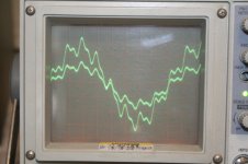
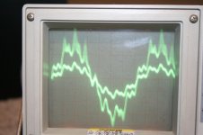
I have run a complex sinewave - 1khz(Ref)+8khz(-15db)+16khz(-20db)
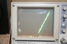
and a simple Sine wave at 30khz
I plotted an unloaded input (other channel) vs an unloaded output (No speaker) for each as well as an XY plot (hoping to show linearity/distortion)
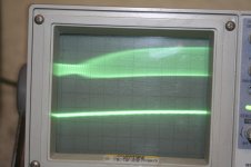
What I get is this, For unloaded output the voltage values look really clean for both signals, and at 30khz the XY is a faint ellipse (showing some phase shift) probably <10deg. Plots are below...
Unfortunately for loaded output (just speaker, no zobel) the small signal response looks ok, but for any significant load the output voltage starts to "smear" on the oscope output, distortion/oscillation I assume... You can see this on the last picture. I don't know if its just me not knowing how to use the oscope correctly, or if its really something wrong with the output.
Is this just because I don't have a zobel? Maybe I need more outputs? But the voltage levels are still quite low < 10V pk. Basically I'm worried about packaging this setup because I don't want to finalize anything that's got a problem.
ksa992FTA/ksc1845FTA for the input level
Ksc3503ESTU for the EF Vas
Ksc2690AYS and Ksa1220YSTU for the drivers
MJL4302A/4281A Outputs
I used .1ohm output resistors and I don't have a zobel network.
I've created some inputs for the amp and I'm trying to determine if it is properly stable or what I need to do to make it so. I got a program on the internet to output signals from my sound card like a signal generator, they aren't as good as a really nice generator, but I hope to tell something from them. Hopefully you guys can help...
I have run a complex sinewave - 1khz(Ref)+8khz(-15db)+16khz(-20db)
and a simple Sine wave at 30khz
I plotted an unloaded input (other channel) vs an unloaded output (No speaker) for each as well as an XY plot (hoping to show linearity/distortion)
What I get is this, For unloaded output the voltage values look really clean for both signals, and at 30khz the XY is a faint ellipse (showing some phase shift) probably <10deg. Plots are below...
Unfortunately for loaded output (just speaker, no zobel) the small signal response looks ok, but for any significant load the output voltage starts to "smear" on the oscope output, distortion/oscillation I assume... You can see this on the last picture. I don't know if its just me not knowing how to use the oscope correctly, or if its really something wrong with the output.
Is this just because I don't have a zobel? Maybe I need more outputs? But the voltage levels are still quite low < 10V pk. Basically I'm worried about packaging this setup because I don't want to finalize anything that's got a problem.
Attachments
Last edited:
Yes put the zobel in.
It looks like you've got a bit of cleaning up to do.
A schematic with all the component value posted would be necessary for anyone to help you with this.
Stick to a simple sine wave for now.
Is the sine wave you've shown both the input and output signal?
The traces are too thick possibly indicating some high frequency components, or it might just your test setup.
Post a pic of your layout as well.
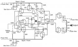
Sorry for the awkward setup, but the layout on the schematic is representative of the layout on the board, I used it to place the components.
All the PNP transistors are Left flat and all the NPN's are Right flat. In reality I have changed the drivers and the VAS so they no longer look like a TO-92 package but I left the drawing as it was before.
All the PNP transistors are Left flat and all the NPN's are Right flat. In reality I have changed the drivers and the VAS so they no longer look like a TO-92 package but I left the drawing as it was before.
Attachments
Hi Buzz1167,
I'm not used to seeing schematics drawn this way, but it's ok I can wrap my head around it.
I don't have a lot of time today to study this. I'll have a closer look at it later.
One thing that stands out to me is the omission of resistors between the driver transistor emitters and the output node. These resistor are necessary with an EF stage. Without them you can get a bit of high frequency oscillation occurring. The driver transistor emitter resistors are typically between 100 to 200 ohms. This is a good starting value. The end value depends on the amount of standing idle current the designer whats in the drivers. This depends partly on the transistor selection and the amount of bias current set in the output transistors.
I suggest adding the emitter resistors in and a zobel network as well. Be sure to place your zobel downstream from your feedback take off point.
If you are working the amplifier outside of a chassis, make sure you have the heat sink grounded. Any large surface area acts as an antenna for RF electrical noise in the environment.
Good luck with this,
David.
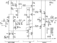
I've added a pic of what I went off of when I started the project.
I have tried to add that resistor (200R) between the bases of the output transistors. When I did I got a high frequency oscillation, observable with the oscilloscope at the shortest time interval (couple waveforms at .05us setting).
I also tried adding a .22uf cap across it as well which made the oscillations, unfortunately, more audible.
Also, I have multiple heat sinks, one for each power supply. So the heatsink is actually "powered". The goal was to attach the transistors per heat sink and have a "collector +" and "collector -" heat sink thus also sharing the power. I didn't previously know that grounding the heatsink was commonplace so I didn't purchase any electric insulating pads for the transistors.
Attachments
Hi Buzz,
That resistor/cap is vital... if it made matters worse you have other issues.
The problems you are experiencing (as said before in the other thread) will be down to layout and wiring details... and maybe the "live " heatsinks too.
I'm sorry we can't be more help... you must build it correctly. The amp is a fully worked example and it performs well. It needs no modifications or alterations. I built this amp on proper PCB's when it appeared 15 or so years back and used it for several years.
Buzz... can you show us a photo of the amp... not saying it will help but we might spot something in your wiring.
When I first started building amps I went through all this, instability, oscillating, amps that were "nearly" right but that had weird problems such as oscillation under load on one side of the waveform. There's no magic fix... it's a steep learning curve, heck I'm still learning now after making it a career")
When I first started building amps I went through all this, instability, oscillating, amps that were "nearly" right but that had weird problems such as oscillation under load on one side of the waveform. There's no magic fix... it's a steep learning curve, heck I'm still learning now after making it a career
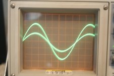
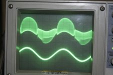
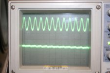
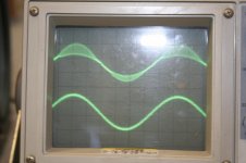
Ive got a little better using the oscope so I got some better pictures, 30khz sine. Close up showing the oscillation everywhere with the 200ohm resistor.
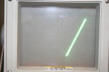
The final pic that has less oscillation is simply with the 200ohm removed...
What would you like to see for the picture of the amp? I don't know whats going to help you. Since I don't have a prototype board I don't have a layout schematic, its just the same "hole board" I was using before.
To be honest, I can't really distinguish the oscillation without the 200ohm from audio, but with it, something does sound wrong in the high frequencies. Although hopefully it will just sound better all around when it stops this non-sense.
By the way, Listening to a 30khz signal for 5 or so minutes while setting this is really messes with your ears after you turn it off... It was weird...
Thanks again,
Attachments
Last edited:
Also, I have multiple heat sinks, one for each power supply. So the heatsink is actually "powered". The goal was to attach the transistors per heat sink and have a "collector +" and "collector -" heat sink thus also sharing the power. I didn't previously know that grounding the heatsink was commonplace so I didn't purchase any electric insulating pads for the transistors.
Hi Buzz1167,
Don't do this. You have put two big antennas connected directly to the collectors of your output transistor. Your are injecting RF and other electrical noise directly into you power rails. This is asking for trouble.
RF likes to travel on the surface of things regardless if those things are grounded. But grounding dose attenuate RF greatly and prevents the RF from becoming an electrical current in a conductor. The best thing for RF interferance is is grounded shielding. However, even a transmitter of 5 Watts at close proximity can penetrate shielding.
Do invest in some insulators for the output transistors and the drivers should be on heat sinks as well. The EF darlington configuration is not known to be the most thermally stable arrangement.
I agree with Mooly, the emitters resistors are a must have and if putting them in makes things worse then the cause is something else. Have you put the zobel in?
You've got to get this oscillation out. It will severely effect the performance and stability of the amp.
David.
Last edited:
Ive got a little better using the oscope so I got some better pictures, 30khz sine. Close up showing the oscillation everywhere with the 200ohm resistor.
The final pic that has less oscillation is simply with the 200ohm removed...
What would you like to see for the picture of the amp? I don't know whats going to help you. Since I don't have a prototype board I don't have a layout schematic, its just the same "hole board" I was using before.
To be honest, I can't really distinguish the oscillation without the 200ohm from audio, but with it, something does sound wrong in the high frequencies. Although hopefully it will just sound better all around when it stops this non-sense.
By the way, Listening to a 30khz signal for 5 or so minutes while setting this is really messes with your ears after you turn it off... It was weird...
Thanks again,
You might consider getting an 8 ohm load resistor for testing. You can get hearing damage from high level frequencies in the ultra sound band. Be careful.
I am curious as to why you are testing at such a high frequency. 1 khz is usually good enough until you have everything working. Also 30khz would heat up the resistor in a zobel network if you had one connected.
David.
Right, No zobel yet. I will buy the components this weekend from mouser and have them for next weekend. I think this really could be a major player. Although not being able to hook up the 200ohm resistor worries me.
Any suggestions on what to use to isolate the transistors from the heatsink, I don't have any useful knowledge of thermal padding manufacturers or where to get it.
No reason for testing at 30khz, just randomly chose a number, figured the higher it was the more pissy the amp might get, thus the high frequency.
I have directly tested that the amount of load is directly proportional to the oscillation though. I have 2 bookshelf speakers, I hooked them up one at a time and then in parallel and there was an obvious increase while they were in parallel. All the oscillation went away while they were disconnected.
Right, No zobel yet. I will buy the components this weekend from mouser and have them for next weekend. I think this really could be a major player. Although not being able to hook up the 200ohm resistor worries me.
Any suggestions on what to use to isolate the transistors from the heatsink, I don't have any useful knowledge of thermal padding manufacturers or where to get it.
No reason for testing at 30khz, just randomly chose a number, figured the higher it was the more pissy the amp might get, thus the high frequency.
I have directly tested that the amount of load is directly proportional to the oscillation though. I have 2 bookshelf speakers, I hooked them up one at a time and then in parallel and there was an obvious increase while they were in parallel. All the oscillation went away while they were disconnected.
The increase of oscillation with increase of load is to be expected. It's proportional to the load current.
What bias current is set in the outputs. I've had some output stages oscillate because of no bias current.
You can order mica or aluminum oxide insulators for the transistor case you're using from Mouser(Page 2006). You will also need some thermal grease (compound) (Mouse # 532-249) and you might consider some mounting clips if your using the plastic flat packs.
If the transistor hole is not insulated from the collector you will need some exstruded nylon shoulder washers as well. Look under thermal management category, mounting kits @ mouser.
David
Thank you for the info, I'll look for the insulators tonight on mouser.
What about the inductor? I went on wikipedia and found a lot of equations for "seemingly" the same thing. Doug's recommendation of 10turns at 1"diam seem to work out around 70-80mH unless I'm missing something. Should I go buy some solid conductor to make it? I assume it will need to carry sufficiently large amounts of current, in the realm of amps right?
I have a mounting solution on my heatsinks, although it could use some work probably so I'll see why they have to offer there as well.
The bias current wasn't set very accurately, I simply put about the right voltage on the output transistors and backed it off a bit since I don't have any thermal compensation right now, under inspection after the amps been running for the last hour, the current through the emitter resistor was around 6ma with no signal (Using just a multimeter and assuming the resistance was exactly 0.1) and the transistors were not hot to the touch, maybe a bit warm, but its warm in the room too; near ambient we'll say.
But I would mention that I was testing it colder than this before, I.E. just turned it on... I really thought that the class B bias would only create crossover distortion, but I haven't seen any indications of that so far on the oscope.
Lineup...
Why do you say that you would never test an amp without a zobel? What do you believe to be wrong with just hooking a test speaker up to the output? I don't want to be dangerous, but I don't see how I am, so please enlighten me if you can. I'll describe what I do to test below...
I generally have 3 speakers for test, 2 bookshelves and a cheap center channel from a long time ago. For the first go at something I'll use the center channel (major rehaul) with a small power supply, then I'll use 1 bookshelf (so I'll only blow one if something goes wrong), and finally change the power supply, try the 1 bookshelf again and then both bookshelves in parallel or series for testing different loads...
So I've been running a 4ohm load with two 30V power supplies for the last few hours pretty constantly, not at full power, but at a reasonable volume... I don't actually know how close I am to clipping but its certainly not an obvious clip anywhere.
I stop and check every once and a while for a silence test, see how much hiss there is, but right now its a pretty tiny level of hiss certainly not audible from any distance other than with your ear to the tweeter.
On another note:Thanks to all who helped me get this far.
Last edited:
Thank you for the info, I'll look for the insulators tonight on mouser.
What about the inductor? I went on wikipedia and found a lot of equations for "seemingly" the same thing. Doug's recommendation of 10turns at 1"diam seem to work out around 70-80mH unless I'm missing something. Should I go buy some solid conductor to make it? I assume it will need to carry sufficiently large amounts of current, in the realm of amps right?
I have a mounting solution on my heatsinks, although it could use some work probably so I'll see why they have to offer there as well.
The bias current wasn't set very accurately, I simply put about the right voltage on the output transistors and backed it off a bit since I don't have any thermal compensation right now, under inspection after the amps been running for the last hour, the current through the emitter resistor was around 6ma with no signal (Using just a multimeter and assuming the resistance was exactly 0.1) and the transistors were not hot to the touch, maybe a bit warm, but its warm in the room too; near ambient we'll say.
But I would mention that I was testing it colder than this before, I.E. just turned it on... I really thought that the class B bias would only create crossover distortion, but I haven't seen any indications of that so far on the oscope.
6mA is plenty.
The addition of an output inductor shouldn't have a significant effect on the oscillation I'm seeing. Although it will help. The inductor prevents oscillation under heavy capacitive loading or short circuits and kills the tuned resonance of the speaker cables connected to the output. Speaker cables behave as antennas. The zobel should take care of most of that. Some people don't like output inductors because it messes up the damping factor. Others will insist that an output inductor is critical and should not be omitted.
David.
Why not Zobel?
When it does not hurt.
I tell you I never would test amplifier with any loudspeaker (crappy or expensive) without Zobel,
because I have done this a few times
... and there was no other option but to put in a ZOBEL
to get things start working normal.
And I repeat my question:
- Why NOT Zobel?
- What is the big drawback?
- Status
- This old topic is closed. If you want to reopen this topic, contact a moderator using the "Report Post" button.
- Home
- Amplifiers
- Solid State
- New amp testing, Noob needs input.