Hello everybody!,
I'm new here and I have a few questions about my leach low tim amplifier.
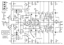
So, I made my own circuit boards using Dr. Leachs provided trace pattern. Got all the components on the board and started to run through the board test procedure that he has provided. I tack soldered the two 100 ohm resistors from the output to both sides of R36, and the jumper in parallel with C12. Then when I get to the instruction that says to apply the 1khz signal to the amp board, and monitoring the output with a scope, I get nothing, absolutely nothing on the output. He says that it should take no more than 25ma, but when I did it, it took 80ma. Where did I go wrong, or what should I do?
Have I made a beginner error? Keep in mind Im 16 and have only had a few years of electronics experience

I'm new here and I have a few questions about my leach low tim amplifier.
So, I made my own circuit boards using Dr. Leachs provided trace pattern. Got all the components on the board and started to run through the board test procedure that he has provided. I tack soldered the two 100 ohm resistors from the output to both sides of R36, and the jumper in parallel with C12. Then when I get to the instruction that says to apply the 1khz signal to the amp board, and monitoring the output with a scope, I get nothing, absolutely nothing on the output. He says that it should take no more than 25ma, but when I did it, it took 80ma. Where did I go wrong, or what should I do?
Have I made a beginner error? Keep in mind Im 16 and have only had a few years of electronics experience
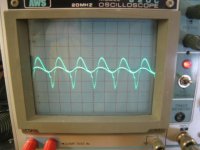
Umm how do you upload pictures to it, I have them on an sd card, but when I click insert, it asks for the url of the page where the picture is, what do I do? Anyways, after a few hours of tinkering and whatnot, they kinda both work. But...after a few minutes the output slowly starts to diminish to nothing... I have the same problem on both of them. Then if you increase the voltage it will rise back up again, then do the same thing, diminish to nothing. ????
Umm how do you upload pictures to it, I have them on an sd card, but when I click insert, it asks for the url of the page where the picture is, what do I do? Anyways, after a few hours of tinkering and whatnot, they kinda both work. But...after a few minutes the output slowly starts to diminish to nothing... I have the same problem on both of them. Then if you increase the voltage it will rise back up again, then do the same thing, diminish to nothing. ????
You need to put the pictures on your website and then use a URL to the pictures on here.
Check that your pics meet the standard limits set by the Forum.
If they don't then crop them to what WE NEED to see. Compress them with suitable software. check what they look like after doing that. Look at reducing the pixel count and compress again. check the pic quality.
Put the compressed, minimum pixel count, cropped pics into your desktop (or any where else where you can locate them quickly).
Attach each pic to your post.
Last edited:
Check that your pics meet the standard limits set by the Forum.
If they don't then crop them to what WE NEED to see. Compress them with suitable software. check what they look like after doing that. Look at reducing the pixel count and compress again. check the pic quality.
Put the compressed, minimum pixel count, cropped pics into your desktop (or any where else where you can locate them quickly).
Attach each pic to your post.
Hear hear ! well said Andrew, nothing worse than those threads that expand the margins and take all day to load even with a high speed connection.
a few 100's kb at most is normally good enough.
To add a photo,
First click "go advanced" in the box below the "quick reply" message box. Doesn't matter if you decide half way through a message to do that, it carries it foward.
Then click "Manage attachements"
Click browse in the first box at the top and find your picture. Repeat for any more pictures.
Click upload... a message appears "uploading"
When complete, scroll down to the bottom of page and click "close this window"
The pictures should now be attached and when you post will appear. I don't think they show in message preview... they never used to anyway.
Make sure your pics aren't too big, a couple of 100k is plenty, and many object when they are massive and it alters the margins
It tells you in the attachments window what max sizes are allowed.
Don't put them onto a website and link to them to avoid staying within the Forum's limits.You need to put the pictures on your website and then use a URL to the pictures on here.
They still download (if that facility is not turned off) and still take time to download and get lost when the weblink gets broken.
AndrewT: During the time its on, I felt around, and didn't detect any heat. But, I will try again tomorrow.
Damon Hill: No the bias diodes are not installed, Mr. Leach's board test procedures said nothing of that, but should they be???...Also, in the board test instructions, Mr. Leach says to tack solder a jumper in parallel with c12, which if I understand would, bypass the bias circuit???
Thanks, Andy
Damon Hill: No the bias diodes are not installed, Mr. Leach's board test procedures said nothing of that, but should they be???...Also, in the board test instructions, Mr. Leach says to tack solder a jumper in parallel with c12, which if I understand would, bypass the bias circuit???
Thanks, Andy
Attachments
I see the input is DC coupled... that's fine as long as you understand the implications but for testing I would add a small cap (0.1 to 1uf poly, not electrolytic as any fault could reverse bias it).
Good advice from nattawa... I would also add to check and measure the voltage across R21 and 22 (the constant current sources) and see if these change as the problem appears.
The DC voltages will reveal the problem.
Good advice from nattawa... I would also add to check and measure the voltage across R21 and 22 (the constant current sources) and see if these change as the problem appears.
The DC voltages will reveal the problem.
Hi,
the jumper sets the bias voltage to zero volts.
That ensures that the output stage passes zero bias current.
The amp is then worse than a ClassB since there will be a small range of input voltage for which there will be no corresponding output voltage.
Read the whole Leach paper on his design. Read it until you almost know it off by heart.
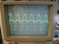
nattawa: The sensitivity is the same for both channels. One is the input, the other is the output of the amp. Excuse my unknowingness, but how do you calculate the voltage gain?
 Also, the supply voltage was 25v. I will measure the voltages across those capacitors and report back.
mooly: Thank you for the tip. Also, I will measure the voltage across those resistors and report back also.
AndrewT: Thank you for clearing that up for me. I have read the whole paper twice now
.
Thanks again to all for the help so far. I would barely get anywhere by myself. This is a great website!
Thanks
Andy
mooly: Thank you for the tip. Also, I will measure the voltage across those resistors and report back also.
AndrewT: Thank you for clearing that up for me. I have read the whole paper twice now
Thanks again to all for the help so far. I would barely get anywhere by myself. This is a great website!
Thanks
Andy
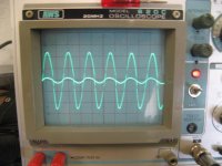
A Leach amp has a voltage gain of about 21 by design. You should be seeing an output waveform with amplitude about 20 time as high as the input waveform in your test. However from your first picture you seemed to have a gain of only about 10 by comparing the height of the waveforms, so I was suspecting either the scope had different sensitivity settings between the channels, or the amp had something not right. No rush. While you're at measuring the DC voltages you might want to double check all the PNPs and NPNs are where they should be.
Also, the supply voltage was 25v. I will measure the voltages across those capacitors and report back.
Andy
Why is the supply only 25v. You need more than that for the input stage to kick in.
Its at 25v because I was afraid that something might go wrong, since the output would go out, but i shall raise the supply voltage. Also, on r21 and r22 when you power it up the dc voltage on r21 is slowly decreasing and the dc voltage on r22 is slowly rising. Then when the "phenomenon" occurs, there is quick drop of voltage on r21 and a quick increase on r22. I noticed that if the two voltages were added together it would equal the supply voltage.
Thanks
Andy
Thanks
Andy
- Status
- This old topic is closed. If you want to reopen this topic, contact a moderator using the "Report Post" button.
- Home
- Amplifiers
- Solid State
- need help with leach amplifier