Hi all,
I have a JVC AX550bk (90wrmsx2) late 80's model amp with a troubled right channel. When the right speaker is connected there is extremely low volume audio which it gets distorted as the volume is turned up. Left channel is working as normal.
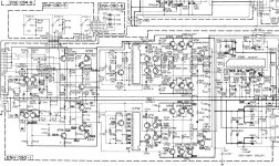
It has a toshiba output pair 2sb755/2sd845 (i.e.: Q761-Q764 in the schematic {around the centre-top-right of diag.}). I haven't pulled these (or any of the output resistors) out to check yet but is there any obvious signs of what might be the problem from the above.
A schematic of the power amp section is attached below.
Please let me know if need a full schematic!
I have a JVC AX550bk (90wrmsx2) late 80's model amp with a troubled right channel. When the right speaker is connected there is extremely low volume audio which it gets distorted as the volume is turned up. Left channel is working as normal.
It has a toshiba output pair 2sb755/2sd845 (i.e.: Q761-Q764 in the schematic {around the centre-top-right of diag.}). I haven't pulled these (or any of the output resistors) out to check yet but is there any obvious signs of what might be the problem from the above.
A schematic of the power amp section is attached below.
Please let me know if need a full schematic!
Attachments
Hi all,
I have a JVC AX550bk (90wrmsx2) late 80's model amp with a troubled right channel. When the right speaker is connected there is extremely low volume audio which it gets distorted as the volume is turned up. Left channel is working as normal.
It has a toshiba output pair 2sb755/2sd845 (i.e.: Q761-Q764 in the schematic {around the centre-top-right of diag.}). I haven't pulled these (or any of the output resistors) out to check yet but is there any obvious signs of what might be the problem from the above.
A schematic of the power amp section is attached below.
Please let me know if need a full schematic!
seems like a driver / pre driver failure, the outputs are underbiased i.e. reason for low volume , starts distorting as the signal level increases.
Thanks for the replies!
@Mooly: I will have the voltage across the E.resistors (R773, R767, R765) checked soon and post. What do you refer to when you say 'supply to the drivers'. Is it the raw power supply to the amp board?
@sasmit: By driver and predriver do you mean the output pair 2sb755/2sd845? sorry about the confusion.
Thanks
Another thing I found was when speakers are disconnected and when listening off the headphones only, both channels seem to work as normal (although r.ch is at slightly less output than L.ch). But as soon as the right speaker is conneted, both the R.speaker and headphone right channel are both low volume and highly distorted. Hope this gives a clue as to what the problem might be.
Another thing I found was when speakers are disconnected and when listening off the headphones only, both channels seem to work as normal (although r.ch is at slightly less output than L.ch). But as soon as the right speaker is conneted, both the R.speaker and headphone right channel are both low volume and highly distorted. Hope this gives a clue as to what the problem might be.
This is typical of what I suggested earlier, when you're loading up the output transistors it is not able to drive the load because of very little base current. The same isn't a problem when driving headphones. This means the pair of transistors or may be one of the pair that drives the output transistors is not supplying enough current to the output transistors. Let me have a thorough look at the schematic and find out the driver pair.
Thanks for the replies!
@Mooly: I will have the voltage across the E.resistors (R773, R767, R765) checked soon and post. What do you refer to when you say 'supply to the drivers'. Is it the raw power supply to the amp board?
@sasmit: By driver and predriver do you mean the output pair 2sb755/2sd845? sorry about the confusion.
Thanks
No the drivers / pre drivers would be 2sc2235 and 2sc2240.
No the drivers / pre drivers would be 2sc2235 and 2sc2240.
have a look at this
http://www.toshiba.com/taec/components2/Datasheet_Sync//66/7723.pdf
Supply to drivers means supply on collectors of Q753 and Q757, and Q755 and Q759.
I would expect around 40 to 60 millivolts across R773 measured between the two end leads (Im assuming it's a 3 legged component and not two individual resistors)
Until that's confirmed you can't go any further.
I would expect around 40 to 60 millivolts across R773 measured between the two end leads (Im assuming it's a 3 legged component and not two individual resistors)
Until that's confirmed you can't go any further.
ok, i have some of the values and measurements needed ...
The voltage drop across R773 (left ch) appears to be normal. When measured the 3 pins have +13mV; -1mV; -13mv respectively with ref to ground
but R774 (right ch) 3 pin resistor shows -14mV; -14mV; -14mV at all 3 points.
I also measured the spkr output of the unit for left ch at (-1mV DC) and right ch at (-14mV DC)
@Mooly: The 10Ohm resistors appear to be ok (R769-R772).
@Sasmit: I only managed to measure one driver pair (i.e.: 2sc2235/2sa965)
The readings are (measured with ref to ground):
Left channel --> Q757 (2sc2235): B: 1181mV C: 54V E: 620mV
Q759 (2sa965): B: -1140mV C: didn't measure E: -588mV
Right channel --> Q758 (2sc2235): B: 1233mV C: 54V E: 688mV
Q760 (2sa965): B: -1140mV C: didn't meas. E: -1142mV
Hope this is clear enough. I will measure the pre-drivers (2sc2240/2sa970) asap and post the values soon and also measure the collectors of the 2sa965's.
Does the fact that there is -14mv Dc on the output of the right ch mean that the output stages also need to be checked or are they safe.
And from this I can see that at the emitter of Q760 (right) does not match the emitter output of Q759 (left). Theres about a 500mV difference. Does this provide any telltale signs of the problem.
Thanks for any input. Much appreciated.
You definitely need to recheck Q760 readings. The fact B and E are the same points to a problem.
Measuring base emitter volt drops is very revealing but is best done actually measureing across the junction where you should always see around 0.65 to 0.75 volts.
With the amp off just see if that B-E junction reads short circuit or very low on ohms/diode check.
Also") , the same applies for the volt drop across the 3 legged resistor... it's not just the voltage relative to ground that we want, it's the volt drop across it by which means we can work out the current and see if the oputput stage is conducting correctly.
, the same applies for the volt drop across the 3 legged resistor... it's not just the voltage relative to ground that we want, it's the volt drop across it by which means we can work out the current and see if the oputput stage is conducting correctly.
Measuring base emitter volt drops is very revealing but is best done actually measureing across the junction where you should always see around 0.65 to 0.75 volts.
With the amp off just see if that B-E junction reads short circuit or very low on ohms/diode check.
Also
, the same applies for the volt drop across the 3 legged resistor... it's not just the voltage relative to ground that we want, it's the volt drop across it by which means we can work out the current and see if the oputput stage is conducting correctly.You definitely need to recheck Q760 readings. The fact B and E are the same points to a problem.
Measuring base emitter volt drops is very revealing but is best done actually measureing across the junction where you should always see around 0.65 to 0.75 volts.
With the amp off just see if that B-E junction reads short circuit or very low on ohms/diode check.
Also
you need to check the transistors by taking them off the board, cannot check them on the board. Besides B and E most probably are shorted for Q760as @mooly said. Take the transistors out do a thorough diode check of the 2 junctions both ways ( forward and reverse )
Problem found!!!!
I decided to pull out the main PCB board out of the housing have a look underneath the board for measuring.
To my surprise, i found the right ch output pair (2sb755/2sd845) is NOT SOLDERED to the board!!! (the pins were just sitting there not connected to the PCB The previous owner must have purposely done this to stop heavy current flowing through this obviously blown output pair. I checked the pair and both had short circuits between collector and emitter pins (Surely blown??).
So i guess it needs a new output pair (2sc755/2sd845) for the R.ch. Should i replace all four output transistors (left and right ch) to make sure that they come from the same manufacturer, etc.
And i checked the price for each and it seems the 2sd845 is no longer available and 2sc755 is $25 locally. Can someone please suggest a replacement output pair that would be a direct replacement (and hopefully a cheaper 1). Thanks!
I decided to pull out the main PCB board out of the housing have a look underneath the board for measuring.
To my surprise, i found the right ch output pair (2sb755/2sd845) is NOT SOLDERED to the board!!! (the pins were just sitting there not connected to the PCB
The previous owner must have purposely done this to stop heavy current flowing through this obviously blown output pair. I checked the pair and both had short circuits between collector and emitter pins (Surely blown??). So i guess it needs a new output pair (2sc755/2sd845) for the R.ch. Should i replace all four output transistors (left and right ch) to make sure that they come from the same manufacturer, etc.
And i checked the price for each and it seems the 2sd845 is no longer available and 2sc755 is $25 locally. Can someone please suggest a replacement output pair that would be a direct replacement (and hopefully a cheaper 1). Thanks!
Last edited:
I decided to pull out the main PCB board out of the housing have a look underneath the board for measuring.
To my surprise, i found the right ch output pair (2sb755/2sd845) is NOT SOLDERED to the board!!! (the pins were just sitting there not connected to the PCB
So i guess it needs a new output pair (2sc755/2sd845) for the R.ch. Should i replace all four output transistors (left and right ch) to make sure that they come from the same manufacturer, etc.
And i checked the price for each and it seems the 2sd845 is no longer available and 2sc755 is $25 locally. Can someone please suggest a replacement output pair that would be a direct replacement (and hopefully a cheaper 1). Thanks!
If the output pair were not connected, you want to be doubly sure all the transistors before it are fine and aren't driving the output pair into saturation. If your're not able to obtain these transistors locally then you would have to change the output transistors for both left and right channels. If you change the output transistors on only one side you would end up with both channels sounding different.
Also check that the 3 legged resistor is intact and not open circuit.
Although the original outputs have inbuilt "ballast" resistor I'm sure any suitable devices would be OK such as 2SA1386 and 2sc3519.
Drivers and you have lots of choice... although getting them in that package may be an issue for you. You would probably be OK with 2N5551 and 2N5401 but watch the connections.
Attachments

yes i will check all the drivers and the predrivers now after taking each of them out.
Can u recomend a suitable replacement output stage. Would any cheap sanken npn/pnp driver work?
Your criteria for searching a replacement transistor shouldn't start with cheap
, looking at the package of 2sd845, I say you should look for sanken output transistors. You could in practice use any transistor with a matching SOA , but sanken's in simmilar package would save you the trouble of re-drilling the heatsink and other mounting issues. Look at the SOA ( safe operating area ) graphs and beta( DC current gain ) for the transistors you're looking to replace and substitute with simmilar or better. MJL ( 21193 /94 ) will easily do the job but would require some drilling and possibly some new mounting hardware ( mica sheets , washers , M3 screws etc ).- Status
- This old topic is closed. If you want to reopen this topic, contact a moderator using the "Report Post" button.
- Home
- Amplifiers
- Solid State
- JVC amp - Right ch. not working