ok, all driver/predriver transistors have been measured out of the board (q753-Q760) and all seems to be ok. And in the circuit All drivers/predrives show a V(be) of ~0.7V. (my previous reading for Q760 was wrong ") . And all resistors are also showing the rated value out of circuit (R765-R774).
. And all resistors are also showing the rated value out of circuit (R765-R774).
So its just the output pair that needs replacing. What factors should u look for when your looking for replacement output pair (max power, max current, max voltage...)
My previous amp had a sanken mn1620/mp2488 pair. I can source them easily. Would These be ok?
. And all resistors are also showing the rated value out of circuit (R765-R774).So its just the output pair that needs replacing. What factors should u look for when your looking for replacement output pair (max power, max current, max voltage...)
My previous amp had a sanken mn1620/mp2488 pair. I can source them easily. Would These be ok?
My previous amp had a sanken mn1620/mp2488 pair. I can source them easily. Would These be ok?
Quick search and I couldn't find any info on those...
oops sorri, i got them the wrong way round. its MN2488 and MP1620 pair from sanken.
here are the data sheets: http://www.datasheetcatalog.org/datasheets/208/499159_DS.pdf
http://www.datasheetcatalog.org/datasheets/208/500481_DS.pdf
They say a range of values like Vce -150V, Vbe - 5V, Ibmax - 1A, Icmax - 10A, 150W etc. Any clues on which values should be particularly looked at and which are critical? Thanks
Also why are some output pairs with higher power output rating priced at ~$10 (MJ15003 - 250W) and the MJL21193 - 200W priced at ~17. Is it just a matter of quality? Here are the details below:
MJL21193 PNP Transistor
Silicon TypeType Mat Case Diss Vcb Ic Hfe Hfe @25C BiasMJL21193 PNP TO- 264 200W 250V 16A 25/75...$16.90
MJ15003 NPN Transistor (with MJ15004 PNP)
Silicon TypeType Mat Case Diss Vcb Ic Hfe Hfe @25C BiasMJ15003 NPN TO-3 250W 140V 20A 25 5A...$10.90
Some more options i've been looking at:
TIP35C NPN Transistor (with TIP36C PNP)
Silicon TypeType Mat Case Diss Vcb Ic Hfe Hfe @25C BiasTIP35C NPN TO218 125W 100V 25A 20 5A $6.90 (sure looks like a bargain! )
My the amp is actually rated at 90Wrms x 2 and the supply rail is at +/- 50V so shouldn't ~90W ~50V output stages be sufficient or is that not the case.
Sorry about all the questions Much appreciate the help!
MJL21193 PNP Transistor
Silicon TypeType Mat Case Diss Vcb Ic Hfe Hfe @25C BiasMJL21193 PNP TO- 264 200W 250V 16A 25/75...$16.90
MJ15003 NPN Transistor (with MJ15004 PNP)
Silicon TypeType Mat Case Diss Vcb Ic Hfe Hfe @25C BiasMJ15003 NPN TO-3 250W 140V 20A 25 5A...$10.90
Some more options i've been looking at:
TIP35C NPN Transistor (with TIP36C PNP)
Silicon TypeType Mat Case Diss Vcb Ic Hfe Hfe @25C BiasTIP35C NPN TO218 125W 100V 25A 20 5A $6.90 (sure looks like a bargain!
)My the amp is actually rated at 90Wrms x 2 and the supply rail is at +/- 50V so shouldn't ~90W ~50V output stages be sufficient or is that not the case.
Sorry about all the questions
Much appreciate the help!If the supply is -/+50volts then you need at least 100 volt vce rated devices. That's in theory... in practice you need higher due to a breakdown mechanism called "secondary breakdown" which afflicts bjt (normal transistors). Although a device may appear to be within it's ratings, at voltages near vce the device can fail at relatively low levels of IC.
When you need devices rated for 100 volts+ (and that's what they need to withstand as the output swings toward one or the other rails) then they aren't cheap.
The MJ15003/4 are the wrong package I think... T03 ?
When you need devices rated for 100 volts+ (and that's what they need to withstand as the output swings toward one or the other rails) then they aren't cheap.
The MJ15003/4 are the wrong package I think... T03 ?
Ok ,i've decided to go for the sanken mn2488/mp1620 pair. They closely match the values of the originals except for the Hfe and fT.
Original fts are 20Mhz whereas the mn2488/mp1620 are at 55Mhz. And the original beta is at 55min, 160 max whereas the datasheets for mn2488/mp1620 says beta is 5000 min and 300000 max! Fyi the mn2488/mp1620 are a darlington pair.
Original fts are 20Mhz whereas the mn2488/mp1620 are at 55Mhz. And the original beta is at 55min, 160 max whereas the datasheets for mn2488/mp1620 says beta is 5000 min and 300000 max! Fyi the mn2488/mp1620 are a darlington pair.
Ok ,i've decided to go for the sanken mn2488/mp1620 pair. They closely match the values of the originals except for the Hfe and fT.
Original fts are 20Mhz whereas the mn2488/mp1620 are at 55Mhz. And the original beta is at 55min, 160 max whereas the datasheets for mn2488/mp1620 says beta is 5000 min and 300000 max! Fyi the mn2488/mp1620 are a darlington pair.
you might run into oscillations with fT of 55 Mhz, simply looking at the absolute values won't give you the correct picture. check the SOA graph of the transitor from the datasheet at the supply voltages you're expecting them to work. Looking at your original transistor figures MJL21193/94 look better suited for the job. They might even sound better than the original Toshibas
Thank you for the information very helpful
One last question, does the outputs HAVE to be complimentary npn/pnp transistors or can any pnp/npn be used with 'closely matching' (but not complimentary) be used?
It has to be a complementary pair, don't just use any matching pair. It kind of defeats the purpose of this discussion if you just want to use any npn/pnp. It should not only be complementary but you should also replace the output pairs on the other working channel also, so that you don't end up with two different sounding channels.
just a question out of curiosity
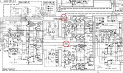
@mooly, sasmit: The amp is running at a voltage of +/-55V as i said before. Would it be possible to reduce that voltage to say around ~35V and use lower rated output transistors (~100V).
If this is possible to be done, then if i change the 33Ohm power supply resistors (R811-R812) to a higher resistance (and power) would that be all thats needed. I've circled it in the diagram. Or is there more needed to be done to the power supply like current limiting, etc...
Attachments
@mooly, sasmit: The amp is running at a voltage of +/-55V as i said before. Would it be possible to reduce that voltage to say around ~35V and use lower rated output transistors (~100V).
You would have to spend far more than some higher rated transistors to reduce the voltage from 55 to 35 ...that will become another project by itself
. Buying a lower rated transformer or a buck regulator either ways it's gonna cost you a lot more than buying some transistors.- Status
- This old topic is closed. If you want to reopen this topic, contact a moderator using the "Report Post" button.
- Home
- Amplifiers
- Solid State
- JVC amp - Right ch. not working