Borc said:You mean use of standard Vbe;
better yet, you could use amplified diodes: tie the base with the collector. it is said to generate sharper cut-off than a traditional diode.
You need only a PN-junction so a normal transistor will do a "diode". You could also use a "normal" Vbe multiplier, two resistors and one transistor. I suppose Prof. Leach has chosen a more complicated Vbe multiplier in order to get a more accurate compensation but the three part solution will also work. Maybe you will get lower currents when the amp is warm, not constant, but this isn't a big disadvantage.Borc said:Hello!
Anyone tried to replace bias diodes which are hard to mount with TO-220 transistors in B-E connection? That will be easier to use with "normal" heatsink.
Re: Re: Leach amp bias diodes
Here is the explanation from Dr. Leach's website of why he chose the diode approach:
I like the idea of having the Vbe multiplier on the circuit board to minimize stray capacitance to ground from the output of the second stage. This leads to better stability. Remember, the second stage sets the dominant pole in the open-loop transfer function. I don't want that transfer function to be a function of unpredictable wiring capacitance to a Vbe multiplier on the heat sink. Therefore, I opted for the diodes on the heat sink. The stray capacitance of the leads to the diodes can be isolated with series resistors. You can't use the series resistors if you put the Vbe multiplier on the heat sink.
peranders said:
I suppose Prof. Leach has chosen a more complicated Vbe multiplier in order to get a more accurate compensation but the three part solution will also work. Maybe you will get lower currents when the amp is warm, not constant, but this isn't a big disadvantage.
Here is the explanation from Dr. Leach's website of why he chose the diode approach:
I like the idea of having the Vbe multiplier on the circuit board to minimize stray capacitance to ground from the output of the second stage. This leads to better stability. Remember, the second stage sets the dominant pole in the open-loop transfer function. I don't want that transfer function to be a function of unpredictable wiring capacitance to a Vbe multiplier on the heat sink. Therefore, I opted for the diodes on the heat sink. The stray capacitance of the leads to the diodes can be isolated with series resistors. You can't use the series resistors if you put the Vbe multiplier on the heat sink.
Re: Re: Re: Leach amp bias diodes
It's correct that stray capacitance is a no good thing, therefore keep the wires short, valid in most parts in the amp.andy_c said:
Here is the explanation from Dr. Leach's website of why he chose the diode approach:
I like the idea of having the Vbe multiplier on the circuit board to minimize stray capacitance to ground from the output of the second stage. This leads to better stability. Remember, the second stage sets the dominant pole in the open-loop transfer function. I don't want that transfer function to be a function of unpredictable wiring capacitance to a Vbe multiplier on the heat sink. Therefore, I opted for the diodes on the heat sink. The stray capacitance of the leads to the diodes can be isolated with series resistors. You can't use the series resistors if you put the Vbe multiplier on the heat sink.
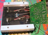
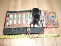
BrianGT said:The diodes aren't that difficult to deal with. Just put them on the heatsink near your devices. Here is a picture of the latest leach amp that I helped a friend build, using newer MJL1302A/3281A devices.
--
Brian
Douglas Self recommended to put the diodes to the top of the output devices. This gives better sensitivity, and less capacity, due the large distance from the heatsink.
Sajti
'Anyone tried to replace bias diodes which are hard to mount with TO-220 transistors in B-E connection? That will be easier to use with "normal" heatsink.'
i actually use the base collector junction, yes it can be done, i find them to be more siensitive due to the nature of construction of the transistor, i use case 77 types mostly....
i actually use the base collector junction, yes it can be done, i find them to be more siensitive due to the nature of construction of the transistor, i use case 77 types mostly....
Re: Re: Re: Leach amp bias diodes
I've been thinking og this stray cap thing. Is _this_ really a problem? Isn't it a bigger problem with an antenna into a sensitive part in the amp?andy_c said:
Here is the explanation from Dr. Leach's website of why he chose the diode approach:
I like the idea of having the Vbe multiplier on the circuit board to minimize stray capacitance to ground from the output of the second stage. This leads to better stability. Remember, the second stage sets the dominant pole in the open-loop transfer function. I don't want that transfer function to be a function of unpredictable wiring capacitance to a Vbe multiplier on the heat sink. Therefore, I opted for the diodes on the heat sink. The stray capacitance of the leads to the diodes can be isolated with series resistors. You can't use the series resistors if you put the Vbe multiplier on the heat sink.
Just one idea:
If we use same PCB az Jens use, and try to apply TO-126 transistor as temperature sensor devices, it't very easy to put to the top of the MJLs. And just one screw can fix both of them. It's will be very sensitive for the temperature, and keep the bias well controlled.
Sajti
If we use same PCB az Jens use, and try to apply TO-126 transistor as temperature sensor devices, it't very easy to put to the top of the MJLs. And just one screw can fix both of them. It's will be very sensitive for the temperature, and keep the bias well controlled.
Sajti
Re: Re: Re: Re: Leach amp bias diodes
I think that the antenna no problem. With carefully designed PCB, wich contains both the thermal sensor, and the output devices, there should be no problem.
TO-126, or TO-220 cases results some capacitance between the transistor and the heatsink. The heatsink is grounded in most of the amplifiers. The capacitance between the bias transistors and the heatsinks makes short circuit for RF.
Sajti
peranders said:
I've been thinking og this stray cap thing. Is _this_ really a problem? Isn't it a bigger problem with an antenna into a sensitive part in the amp?
I think that the antenna no problem. With carefully designed PCB, wich contains both the thermal sensor, and the output devices, there should be no problem.
TO-126, or TO-220 cases results some capacitance between the transistor and the heatsink. The heatsink is grounded in most of the amplifiers. The capacitance between the bias transistors and the heatsinks makes short circuit for RF.
Sajti
Bias diodes
If any of you are interrested I can post the files, the are made i Eagle v. 4.03
What happens if you change the diodes for transistors, except for better thermal contact to the heatsink?
I mounted my diodes on an output transistor because the heatsink weighs 7 kg, and therefor will so long to heat, that output devices are in danger of overheating before the protection circuit ever finds out the amp is hot.
To Per: I dont have a camara at the moment, but I can mail you the files from eagle.
\Jens
peranders said:
I've been thinking og this stray cap thing. Is _this_ really a problem? Isn't it a bigger problem with an antenna into a sensitive part in the amp?
I agree. This looks like it would be a problem with the standard Leach amp layout if one were to try doing the temperature compensation with the Vbe multiplier. But the layout of Jens looks like it's not susceptible to that problem at all.
Until this morning, there were a couple of things bothering me about power amp temperature compensation. After reading the Douglas Self book and looking at the Leach amp schematic, two things specifically had me confused:
First, why does the Leach amp need 4 temperature compensation diodes when it's only compensating 2 junctions (the output stage NPN and PNP)?
Second, when Douglas Self moved the temperature sensor of his test amp from the heat sink to the transistor case, it became overcompensated after this. Why?
It turned out I had been making a bad assumption when I was thinking about it before. Looking at the junction temperature as a function of heat sink temperature, you get:
Tj = Ts + Pd * (theta_jc + theta_cs)
Where
Tj = junction temperature
Ts = heat sink temperature
Pd = power dissipation
theta_jc = thermal resistance junction to case
theta_cs = thermal resistance case to sink
Steady-state temperature is assumed.
The sensor of the Leach amp senses Ts. It looks like the derivative of Ts with respect to Tj is one, right? No. That was my mistake. Ts and Tj are both functions of Pd. So the chain rule must be used as follows:
dTs/dTj = (dTs/dPd) / (dTj/dPd)
Now:
Tj = Ta + Pd * (theta_jc + theta_cs + theta_sa)
So
dTj/dPd = theta_jc + theta_cs + theta_sa
Also
Ts = Ta + Pd * theta_sa
So
dTs/dPd = theta_sa
Taking the ratio of the derivatives gives:
dTs/dTj = theta_sa / (theta_sa + theta_cs + theta_jc)
which can be much less than one. That's why it takes more than 2 diodes to compensate the two junctions of the Leach amp. If we assume that the Leach amp is perfectily compensated (for steady-state), then it follows that:
theta_sa / (theta_sa + theta_cs + theta_jc) = 0.5
Because there's 2 junctions and 4 compensation diodes. In general, you have some probe temperature Tprobe, and the ratio of the change in the probe temperature to the change in junction temperature is less than one. But if you do something to increase dTprobe/dTj, such as moving the temperature sensor from the heat sink to the case, then an amp which used to have optimum compensation could now be overcompensated.
So it's a possibility that Jens' amplifier could end up being overcompensated from putting the diodes on the transistor cases, just as in Douglas Self's experiments. This could cause crossover distortion as the amp warms up. Jens, it might be worthwhile to experiment with 3 diodes instead of 4 if the final position of the diodes ends up being on the transistor case.
The Self amp was overcompensated, because the whole bias network was planned to heatsink mounted sensor.
I think there is no real possibility to plan thermal compensation on paper. There is lot of unknown parameters, and -of course- lot of known.
If You mount the sensor to the top of the output device, You can plan more simple regulating circuit, and can use smaller emitter resistors for the output devices.
Remove one sensor diode from the circuit is not a good solution. But Jens can removes one diode from the case of the MJL, and keep away from the heatsink (2-3cm is enough). If it still too much, do the same with the second one. With 4 diodes there is a lot of possibilities, such as two diodes on the case two on the heatsink etc.
With some bias measuring the bias can adjusted 100% temperature independent.
Sajti
- Status
- This old topic is closed. If you want to reopen this topic, contact a moderator using the "Report Post" button.
- Home
- Amplifiers
- Solid State
- Leach amp bias diodes