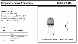
to be more precise see attached picture (from Fairchild datasheet) there is a mistake between pinning description and transistor symbol. I used this and you know the story after.
To resume, I have used bad pinning input for my drawing that's why the ouput arrangement is wrong, the amp is singing because it is correctly wired.
To resume, I have used bad pinning input for my drawing that's why the ouput arrangement is wrong, the amp is singing because it is correctly wired.
Attachments
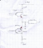
I post the corrected drawing of the output stage using now the correct pin order of BD devices. I hope that makes things clear for everybody. Sorry for the confusion.
The TIP/BD pair is called "inverted Darlington" or "compound" and this output arrangement can perform very well.
Your replies saved me hours of useless work ! Thanks again
The TIP/BD pair is called "inverted Darlington" or "compound" and this output arrangement can perform very well.
Your replies saved me hours of useless work ! Thanks again
Attachments
You are right, it is usual to see emitter resistor but with this kind of arrangement it is usual to see that they don't have. See attached picture of an old famous class A amp design.
No I will not modify this amp for the moment, I keep observing before doing anything.
No I will not modify this amp for the moment, I keep observing before doing anything.
Attachments
Hi DF96,
Thanks for your info. I am not used to this output arrangement.
At low volume the sound can be said OK but when I increase the volume I found the sound of this amp very harsh. Is it due to this output topology? I wonder if replacing BD devices by Toshiba equivalent would improve the sound?
Thanks for your info. I am not used to this output arrangement.
At low volume the sound can be said OK but when I increase the volume I found the sound of this amp very harsh. Is it due to this output topology? I wonder if replacing BD devices by Toshiba equivalent would improve the sound?
Sorry, I can't help you with devices. I am a valve man these days. I'm sure others on here will offer advice.
Personally, I think it is a bad topology as it totally relies on global NFB to work at all. I am not opposed to feedback, as some are, but it has to be applied carefully. NFB should be used to improve a good amplifier, not straighten out a bad amplifier.
Personally, I think it is a bad topology as it totally relies on global NFB to work at all. I am not opposed to feedback, as some are, but it has to be applied carefully. NFB should be used to improve a good amplifier, not straighten out a bad amplifier.
Just to inform that I am happy with the amp sound now! The bias current was not set high enough. It was set around 50ma when I opened the amp to repair it. I found the value usual for a 60W amp and let it as is.
As I did not find on which component to play to improve the sound I finally decided to increase the bias current step by step and now the sound is OK. I guess that this output topology needs high bias current, it is set now at 120 ma. There is some heat.
I am monitoring closely the T° because I do want to smoke this old amp.
A CFP output usually needs a much smaller bias current than you might imagine. 50mA could be too big! 10-20mA might be better. 120mA means it is running partly in Class A, then moving to Class B for bigger signals which will introduce distortion. Douglas Self calls this gm-doubling.
- Status
- This old topic is closed. If you want to reopen this topic, contact a moderator using the "Report Post" button.
- Home
- Amplifiers
- Solid State
- Is this output arrangement OK?