Hello diyAudio
I'm looking for some help with my electronics project.
Since I'm quite new to electronics and especially to audio I cant get it to work the was I want.
The Problem is this:
I have a low power audio source form an audio player on one side and a small 8 Ohm 0.25 W speaker on the other.
The signal is almost loud enough so I don't need much amplification. But I would like to an a volume control.
I have a 10k slide potentiometer I would like to use. It works if I just connect it to the signal. The Problem is that the signal goes from 100% to 0% in the first copple of mm in the potentiometer. I need it to fade from 100% to approximately 20% over the howl range of the potentiometer.
I tried it with a simple 741 op-amp but I must have something wrong in my circuit.
Does anybody have some advice for me?
Is the 741 something that can work?
tanks
Roland
I'm looking for some help with my electronics project.
Since I'm quite new to electronics and especially to audio I cant get it to work the was I want.
The Problem is this:
I have a low power audio source form an audio player on one side and a small 8 Ohm 0.25 W speaker on the other.
The signal is almost loud enough so I don't need much amplification. But I would like to an a volume control.
I have a 10k slide potentiometer I would like to use. It works if I just connect it to the signal. The Problem is that the signal goes from 100% to 0% in the first copple of mm in the potentiometer. I need it to fade from 100% to approximately 20% over the howl range of the potentiometer.
I tried it with a simple 741 op-amp but I must have something wrong in my circuit.
An externally hosted image should be here but it was not working when we last tested it.
Does anybody have some advice for me?
Is the 741 something that can work?
tanks
Roland
Normally a log pot is used to avoid crowding the adjustment range to one end of the travel.
However it is possible to do a good approximation of a log pot by adding a ressitor to your lin pot.
See
ESP - A Better Volume Control
Good luck!
Cliff
However it is possible to do a good approximation of a log pot by adding a ressitor to your lin pot.
See
ESP - A Better Volume Control
Good luck!
Cliff
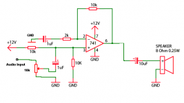
Thx Nrik, it pretty much worked. I did this:
I added two resistors. One to limit the signal going to quiet.
And one to limit the signal strenght a little because it is slightly distortet.
But I think it will work like this if I reexamine the resistors values.
An externally hosted image should be here but it was not working when we last tested it.
I added two resistors. One to limit the signal going to quiet.
And one to limit the signal strenght a little because it is slightly distortet.
But I think it will work like this if I reexamine the resistors values.
The 741 will have a problem driving an 8 ohm speaker. The 100 ohm resistor on the output will certainly limit the output current but will severely limit the available output power. Have you thought about using an LM386 chip rather than the 741? It's designed to drive an 8 ohm speaker and requires fewer parts.
The 741 and similar opamps running on +12Vdc single polarity supply will have ~+1V to +11V output range, i.e 10Vpp.
This is roughly equivalent to 3Vac at the output.
3Vac into an 8ohm load requires an output current of 3V/8r = 0.375Aac.
This is equivalent to 530mApk into the load.
The opamp cannot provide this.
Now we add in the 100r resistor.
3Vac into 108ohm load requires 3V/108r = 0.0278Aac
This is equivalent to 39mApk into the load. Some opamps can provide this most will have entered limiting and/or protection mode.
The 741 datasheet will specify a range of load resistances/impedances that it can drive.
Expect around 1k to 1M not 108r.
You need to look for a high current type opamp or a high current buffer to drive speaker loads even 64ohm speaker loads.
The input volume control is strangled by the series 1k0 resistor in it's tail.
A volume pot can always get to -60dB ref max signal and many will go to lower than -80dB ref max signal.
Adding the 1k0 to the 10k pot limits the minimum volume to ~-20dB ref max signal.
This will act more like a sensitivity control rather than a volume pot.
The two inputs +IN & -IN have different resistances. -IN sees 10k/10k = 5K
+IN sees 10k.
This will result in an output offset that is bigger than the opamp is capable of.
Since the amplifier is AC coupled at both input and output a small output offset is of no consequence, neither to the speaker nor to the sound quality.
However, a big output offset will reduce the maximum signal that can pass without clipping the signal (=more distortion).
with a 10Vpp output and zero output offset the maximum clip free signal is +5Vpk and -5Vpk.
add in a +1V output offset and the maximum output is limited to +4Vpk and -6Vpk (still 10Vpp)
The higher the output offset the worse the clipping of the signal.
Check that the output sits at ~ half the supply voltage for maximum signal transfer.
Send a maximum audio signal through the opamp that is at least 10dB (~1/3 of the voltage) below that 10Vpp capability, i.e. use <3.1Vpp and preferably <1Vpp for 20dB of overhead.
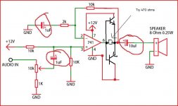
You could add an NPN and PNP transistor to make it workable driving low impedances. Using a 741 or any opamp like this isn't any good for driving a speaker.
The caps circled need increasing in value by a factor of 10 really.
The 470 ohm is to minimise crossover distortion... try it without to hear what this sounds like.
The transistors can be any general purpose types of at least 500 milliamp collector current rating.
The caps circled need increasing in value by a factor of 10 really.
The 470 ohm is to minimise crossover distortion... try it without to hear what this sounds like.
The transistors can be any general purpose types of at least 500 milliamp collector current rating.
Attachments
Only partially satisfied with my results so far I got my hands on a LM386N.
It looked oh so simple with even less additional parts then the 741.
Unfortunately the result hasn't improved...
So let's start from scratch.
If I connect my speaker directly to the source of the audio, the volume and quality are fine.
From here on I would like to use a 20k potentiometer to bring the volume down to 20%.
The 1k resistor in series with the potentiometer is fine for that.
But the audio quality after the 386 is far worse then directly from the source.
I have quite some noise and distortion.
I don't think there can be anything wrong with the circuit because I saw this setup quite some times during research.
Is it possible that I use the wrong capacitors? I used an "Electrolytic Capacitors, Radial 85 °C 220 µF 50 VDC" and a "Ceramic Capacitors 47 nF 50 VDC".
Or is it a problem that my source already has a small amplifier built-in?
An externally hosted image should be here but it was not working when we last tested it.
What's the 200 ohm resistor for? It needs to go.
Doesn't the 386 require a coupling cap on the input when operated on a single supply?
Look at the data sheet. It will probably have a simple amplifier circuit for single sided supply. Use that circuit.
Output coupling cap needs to be doubled at least for 8 ohm operation. Do you understand poles created by coupling caps?
The resistor was there to reduce the nois I have.
This circuit is from the data sheet, which is quite what I did.
I red somewhere else that the LM386 can oscillate if my breadboard wires are too long.
Is that true and how short should they be?
This circuit is from the data sheet, which is quite what I did.
An externally hosted image should be here but it was not working when we last tested it.
Unfortunatley not.Do you understand poles created by coupling caps?
I red somewhere else that the LM386 can oscillate if my breadboard wires are too long.
Is that true and how short should they be?
The resistor was there to reduce the nois I have.
This circuit is from the data sheet, which is quite what I did.
a 200 ohm resistor in series with an 8 ohm speaker? It will reduce noise all right; almost all of the signal will be dissapated across the resistor. Putting resistors in series with a speaker load is a bad idea. An 8 ohm resistor would have reduced "noise" (actually the whole signal) by 3 dB. The place to reduce noise is at the input. A 10K pot on the input should provide a low noise floor, unless of course the pot is faulty.
As far as poles (actually cutoff frequency in layman's terms), a coupling cap or output cap provides a low frequency cutoff point. It works just like crossovers and filters. A 250 uF cap will provide a very high low frequency cutoff point, which may be OK for your application. Look at commercial schematics. Even the very cheapest of the cheap have at least a 470 uF output cap, and "mid-fi" amplifiers will have 2200 or 4700 uF coupling caps.
Well well, seems like the potentiometer was one of my problems.
I restarted from scratch and now it sounds quite different.
If the potentiometer is fully open the sound is not too bad with a little noise.
When I turn it down I get a lot of noise till I can hear nothing else then noise.
I added a picture to illustrate my setup.
I restarted from scratch and now it sounds quite different.
If the potentiometer is fully open the sound is not too bad with a little noise.
When I turn it down I get a lot of noise till I can hear nothing else then noise.
I added a picture to illustrate my setup.
An externally hosted image should be here but it was not working when we last tested it.
With a lash up like that it is very likely that your LM386 is oscillating. "Short leads" means not more than an inch (2.5cm), and less if possible. As far as possible components should be right next to the chip, not on the other side of the breadboard.
Bear in mind that many modern devices use Class D output, with only poor filtering, so you may be feeding a lot of HF hash into your amp. You can't hear it, but your amp is still confused by it.
Bear in mind that many modern devices use Class D output, with only poor filtering, so you may be feeding a lot of HF hash into your amp. You can't hear it, but your amp is still confused by it.
Try adding a cap directly across IC pins 4 and 6 on the breadboard to reduce the impedance of the PSU. Ideally should be something like a 0.1uf paralled by a 100uf but try whatever you have.
Also move the yellow ? speaker ground wire return connection to the extreme top right on your board where the supply enters.
Also move that 10 ohm to the same point.
Also move the yellow ? speaker ground wire return connection to the extreme top right on your board where the supply enters.
Also move that 10 ohm to the same point.
Why are you building this circuit? To learn? You made a few mistakes, and you should have learned a lot from them. I suggest you fiddle with this circuit until you have it mastered, and then move on to a more complicated circuit and master that too. You will learn a whole lot by prototyping circuits on a breadboard. Before you know it, you will have mastered a "keeper" circuit and you can build a permanant version.
Heed this advice; and remember, short leads.
Try adding a cap directly across IC pins 4 and 6 on the breadboard to reduce the impedance of the PSU. Ideally should be something like a 0.1uf paralled by a 100uf but try whatever you have.
Heed this advice; and remember, short leads.
- Status
- This old topic is closed. If you want to reopen this topic, contact a moderator using the "Report Post" button.
- Home
- Amplifiers
- Solid State
- quite simple volume control