That's more or less what I did though my bar was bigger & differently shaped. From that thread, it looks like I could have used a much smaller bar .. but exact details are hidden by the fog of senility.For this reason I've always been very interested in this idea:
http://www.diyaudio.com/forums/pass-labs/149707-another-way-insulate-transistors-heatsinks.html
But now I've found the same can be done without using a heat spreader bar.
This has a substrate that is 3mil Kapton.
That instantly tells me it is a bad Thermal washer.
Please read more carefully. I wrote k52-1. One third the thickness.
What is better?
Best wishes
David
Any one know a lower thermal resistance product?
Best wishes
David
Table 1 from EUVL's Linear Audio Vol 3 article.
Know your literature
")
Jan
Attachments
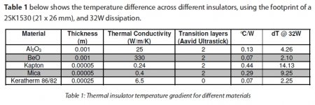
the 1mil and 2mil thickness Kapton will be better.Please read more carefully. I wrote k52-1. One third the thickness.
What is better?
Best wishes
David
But still no better than 1mil mica.
Jan's post shows 2mil Kapton and 2mil mica for comparison.
Table 1 from EUVL's Linear Audio Vol 3 article.
Know your literature
Thanks Jan.
Actually I DO know that one. I read the best literature
But I opened an incorrect folder and and posted the K52-1 when I meant to post the Keratherm. Mea Culpa.
So anyone can beat the Keratherm?
Best wishes
David
Kean, can you tell us how you do this without a heat spreader bar?http://www.diyaudio.com/forums/pass-labs/149707-another-way-insulate-transistors-heatsinks.html
But now I've found the same can be done without using a heat spreader bar.
All you need is a thin film to use as a spacer between the transistor and heatsink. You'll just have to look for thin films around the shop with a micrometer, unless you're willing to buy something online. I found that wax paper had a thickness of 1mil, but that's a pretty questionable material for heatsink interfacing. I never would have thought so, but heavy duty aluminum foil has a thickness of 0.75mil. So I cut out a very small foil washer to fit within the plastic ring around the screw hole in the TO-247 type package. Depending on the transistor package, it may be more convenient to put the foil in other places, for instance in strips along the top and bottom providing those parts are plastic.
I wouldn't try this with an uneven heatsink (or one with deformed screwholes), and I found most of my heatsinks weren't very even when held up to the light to inspect the gap. TO-247 would be most workable for deformed heatsinks since the top and bottom are plastic and it can be supported by foil strips around the edges rather than a washer around the screw.
I wouldn't try this with an uneven heatsink (or one with deformed screwholes), and I found most of my heatsinks weren't very even when held up to the light to inspect the gap. TO-247 would be most workable for deformed heatsinks since the top and bottom are plastic and it can be supported by foil strips around the edges rather than a washer around the screw.
Anodize is not a cost problem in my case.
The elimination of lots of fiddly little washers would be nice.
But not if anodize is as problematic as Andrew and Toni think.
Not sure if you get the concept of "thick" or "hard" anodizing. That's much different from the usual aluminum coating, see the Anodizing Reference Guide. Oxide layers are orders of magnitude thicker and harder than type I or type II. If you can get such hard anodizing for cheap, then definitely use it - and don't forget to post some pictures. You can hope to get a 0.2 C/W improvement in the Rthc-r over the standard greased mica or thin kapton sheet. That would help with a 5-8 degrees case and junction temperature reduction.
Adding another pair to your existing n output devices pairs will lower the junction temperature with as much as P*(Rthj-c + Rthc-r)/(n+1). For say five pairs of output devices (n=5), adding another pair would help as much as a 0.15-0.2 C/W reduction in Rthc-r. That would be about as much as switching from washers to hard anodizing, and if you think this is worth the cost, then again, so be it. But I'm afraid you are as concerned about the heat sink washers as about RHPs in audio amplifiers
 .
.Funny enough (but intuitive if you think it through) lowering the case to heat sink thermal resistance is much more efficient in keeping the junctions cooler for only one or two output pairs.
Last edited:
Thermal interface speed is important indeed.Not sure if you get the concept of "thick" or "hard" anodizing. That's much different from the usual aluminum coating, see the Anodizing Reference Guide. Oxide layers are orders of magnitude thicker and harder than type I or type II. If you can get such hard anodizing for cheap, then definitely use it - and don't forget to post some pictures. You can hope to get a 0.2 C/W improvement in the Rthc-r over the standard greased mica or thin kapton sheet. That would help with a 5-8 degrees case and junction temperature reduction.
Anyway, Tabor Extrusions makes heatsinks with a very thick glossy black oxide coating.
Drilling damages the coating and for example Onsemi outputs that have the plastic plug in the middle of the hole are okay; however, plain devices, such as LM1875 need the hole chamfered. To chamfer a device's mounting hole, you'd get a drill bit three times as big as the hole and drill into the hole on the back side of the device, but just a little bit, not all the way through. When the device is mounted, the little beveled will get filled full of thermal grease, preferably Arctic Ceramique or GC Waldham #44.
Also any sharp corners need sanded smooth prior to pasting and mounting.
Drilling from the fin side works a lot better because it doesn't make a little hill at the hole area, but drilling from the face side is problematic because the hole area gets taller.
The prospect of direct mounting onto oxide is more dodgy (less safe) than mica sheets due to the precision needed and that shipping the finished work may eventually cause contact, which would blow the fuses. It is hard to find the drill bits long enough to do it right.
Here is a chopped bit of a Tabor extrusion:
Aavid Thermalloy - 627253B06000 - Fans, Motors & Thermal Management - Heatsinks - Allied Electronics
An externally hosted image should be here but it was not working when we last tested it.
Probably enough for 160 watt Class AB amp (it would take two for stereo).
Using these to form the sides of the enclosure makes a funny size enclosure, 6" tall, but shallow at 10" deep. I wish they had 4" $24 sections, so much more convenient for me than the 6" $36 sections.
These can be bought from the manufacturer, Tabor, for much less than Aavid's $6 per inch retail price.
P.S.
Personally, I don't direct mount when the amplifier is in metal enclosures because mica is still safer. Even more important than thermal interface speed? Safety is more important (so I use mica). No free lunch.
Last edited:
Hi everyone and sorry for talking about a different matter,
I'm interested in making an amplifier using beta enhanced VAS + cascode, but I was warned by a friend, that said me that it was a discussion between Michael Kiwanuka and Bob Cordell, and it was proved that this topology is locally unstable. I've made the simulations following Michael Kiwanuka's instructions present in his .asc file and I've got the same results 192 degrees of phase shift at 0dB, I've changed this circuit to look a little more like the ones present in Bob's book and I have something between 170-175 at 0 dB which is really bad news
Removing the cascode I still have 166 degrees phase shift at 0 dB, which isn't good enough for me.
What do you think?
Beta enhanced VAS isn't that good?
I've made some experiments and I've noticed that adding base stopper resistors to the EFs seems to help reducing this phase shift problem, but could have other problems, the values should be calculated taking in account cpi(cbe) and cmiu(cbc), and then using 1/(2*pi*Cin*fmax), I've used the following fmax values, 10 MHz for the first EF, 2 MHz for the second, and 1 MHz for the output devices.
I Don't know if this solves the problem, but I think that maybe it's only encovering it. With 2SC/2SA as drivers it's almost impossible to have a low phase shift.
I will post the test circuits latter, and I will also test the effects with mosfets outputs.
Can anyone help me here?
I don't know almost anything about local stabillity.
Thank you very much for your attention,
Best regards,
Daniel
Last edited:
Rubalit, Alunit, Vanadin (Vanadium oxide), Borazon coating (expensiv), Beridox (toxic).Any one know a lower thermal resistance product?
Hi everyone and sorry for talking about a different matter,
I'm interested in making an amplifier using beta enhanced VAS + cascode, but I was warned by a friend, that said me that it was a discussion between Michael Kiwanuka and Bob Cordell, and it was proved that this topology is locally unstable. I've made the simulations following Michael Kiwanuka's instructions present in his .asc file and I've got the same results 192 degrees of phase shift at 0dB, I've changed this circuit to look a little more like the ones present in Bob's book and I have something between 170-175 at 0 dB which is really bad news
Removing the cascode I still have 166 degrees phase shift at 0 dB, which isn't good enough for me.
What do you think?
Beta enhanced VAS isn't that good?
I've made some experiments and I've noticed that adding base stopper resistors to the EFs seems to help reducing this phase shift problem, but could have other problems, the values should be calculated taking in account cpi(cbe) and cmiu(cbc), and then using 1/(2*pi*Cin*fmax), I've used the following fmax values, 10 MHz for the first EF, 2 MHz for the second, and 1 MHz for the output devices.
I Don't know if this solves the problem, but I think that maybe it's only encovering it. With 2SC/2SA as drivers it's almost impossible to have a low phase shift.
I will post the test circuits latter, and I will also test the effects with mosfets outputs.
Can anyone help me here?
I don't know almost anything about local stabillity.
Thank you very much for your attention,
Best regards,
Daniel
Hi Daniel,
Try simulating one of the amplifiers in Chapter 3 of my book using my models. If you poke around in it in an ac simulation I don't think you will find any evidence of instability. Simulate out to 100 MHz closed loop and probe internal nodes, looking for suspicious peaks or dips. Similarly, do a transient simulation with a very low-level non-bandlimited squarewave (avoid slewing) and look for signs of ringing.
Cheers,
Bob
Hi everyone,
Thank you very much for your help Bob Cordell
I will test the amplifier with the output tripple and beta enhanced VAS + cascode.
Best regards,
Daniel Almeida
Why ??, the cascoding could make the performance worse instead of improving it. Look at the effects of vas loading and input and output impedance of the vas, then youll understand why its really not a good idea.
Cascodes in the input stage and VAS/TIS help enormously with power supply rejection. Stability of the compensation loop is then an issue, but the loop can be compensated with a judiciously placed series-RC network to ground at the VAS/TIS output or elsewhere. Edmond Stuart has even suggested a method to bootstrap this network to reduce its loading effects.
Cascodes in the input stage and VAS/TIS help enormously with power supply rejection.
Cascodes in the input stage give measurable benefit in THD and don't cuase much complication. Almost a no brainer from my beginner point of view.
I'm really struggling to justify the three transistor VAS on the grounds of complexity but my mind is still open
Regarding the PSRR benefits, would a cap multiplier on the power rails give similar benefits but without affecting loop stability?Cascodes in the input stage and VAS/TIS help enormously with power supply rejection. Stability of the compensation loop is then an issue, but the loop can be compensated with a judiciously placed series-RC network to ground at the VAS/TIS output or elsewhere. Edmond Stuart has even suggested a method to bootstrap this network to reduce its loading effects.
Once again cascodes in input stages could actually make performance worse if you dont know what to look for. Its true that cascoding improves PSRR but is it necessary when youre already 80 db plus. Amps with lower PSRR than that work and sound just fine.
Once again cascodes in input stages could actually make performance worse if you dont know what to look for. Its true that cascoding improves PSRR but is it necessary when youre already 80 db plus. Amps with lower PSRR than that work and sound just fine.
In my experience the cascode for the VAS does not bring as much to the table as the emitter follower in front of it. However, the cascode benefits depend on the type of VAS transistor being used; some VAS transistors with relatively small Early voltage will be helped a lot. It is also true that the improvement of a cascode may be swamped out if the output stage is just a double, due to the loading that the output stage puts on the VAS anyway. The cascode can also allow the main VAS transistor to operate at lower Vce, reducing its dissipation. So, depending on the specifics of your amplifier, YMMD in regard to the addition of a cascode.
Cascodes in the input stage also allow the use of lower-voltage devices in the input LTP. This can be especially helpful in amplifiers with JFET inputs.
Cheers,
Bob
Hi everyone,
Thank you all for your help,
In the amplifier that I'm projecting I've good phase/gain margins, but I've never tested the internal nodes to check for local stability, how this can be made, I've read the section of your book where you talk about that, you say that the internal node should be tested with a signal injected by a voltage source thru a 10Mohm resistor, but using this procedure and probing this same node I've strange results.
Can you explain to me better how to test the internal nodes to evaluate local stability? Please?
I've a doubt, what happens if an amplifier is globally stable, due to high frequency roll-offs like gate/base stopper resistors at the OPS and capacitors or zobel networks from gate to drain (base to collector), and it has local instability, for example in the VAS, this can lead to some kind of problem? What can go wrong? The amplifier could be destroyed?
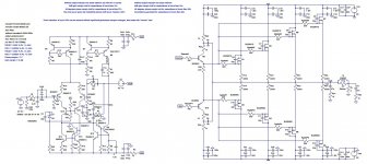
Attached to this post is a picture of the circuit, LTSpice circuit (.asc file) and your models including the lateral MOSFET output devices.
This amplifier is based on the amplifiers present in your book, and in designs like the Honey Badger by Peter V (ostripper) and astx (some ideas from his amplifier with the double EF stage), mcd99uk is also now helping me with some questions related to this design, I've learned lots of tricks, and I've made lots of improvements to my design with his help
Attached is a figure of my circuit with and without the cascode at the VAS, the LTSpice (.asc files) and the your models with the lateral MOSFETs models included.
If you are interested in know more about the amplifier that I'm projecting, the thread associated to it is "How to make a low distortion lateral MOSFET amplifier?".
Thank you very much for your attention,
Best regards,
Daniel
Thank you all for your help,
In the amplifier that I'm projecting I've good phase/gain margins, but I've never tested the internal nodes to check for local stability, how this can be made, I've read the section of your book where you talk about that, you say that the internal node should be tested with a signal injected by a voltage source thru a 10Mohm resistor, but using this procedure and probing this same node I've strange results.
Can you explain to me better how to test the internal nodes to evaluate local stability? Please?
I've a doubt, what happens if an amplifier is globally stable, due to high frequency roll-offs like gate/base stopper resistors at the OPS and capacitors or zobel networks from gate to drain (base to collector), and it has local instability, for example in the VAS, this can lead to some kind of problem? What can go wrong? The amplifier could be destroyed?
Attached to this post is a picture of the circuit, LTSpice circuit (.asc file) and your models including the lateral MOSFET output devices.
This amplifier is based on the amplifiers present in your book, and in designs like the Honey Badger by Peter V (ostripper) and astx (some ideas from his amplifier with the double EF stage), mcd99uk is also now helping me with some questions related to this design, I've learned lots of tricks, and I've made lots of improvements to my design with his help
Attached is a figure of my circuit with and without the cascode at the VAS, the LTSpice (.asc files) and the your models with the lateral MOSFETs models included.
If you are interested in know more about the amplifier that I'm projecting, the thread associated to it is "How to make a low distortion lateral MOSFET amplifier?".
Thank you very much for your attention,
Best regards,
Daniel
Attachments

- Home
- Amplifiers
- Solid State
- Bob Cordell's Power amplifier book