Hi Bob
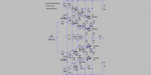
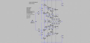
I was thinking about this example of cascode power output stage, I cannot calm it
Hi Pawel,
I am on my way to a mini-vacation, so I may not be able to respond for a few days.
Cheers,
Bob
if you could suggest how fight the oscillation...
If randomly chosen miller caps don't work, try randomly chosen RCs with an Fc below that of your oscillation frequency. I found this stopped oscillation. More RCs might improve phase linearity.
Attachments
Pavel, what you show is a theoretical circuit with ideal current & voltage sources.but dear Edmond, if you could suggest how fight the oscillation...
But everything else that connects to the circuit also affects stability.
If you want sensible advice, you need to show us the real thing including details of earthing and decoupling.
I just found this really great paper on ferrites and RFI protection!
http://audiosystemsgroup.com/SAC0305Ferrites.pdf
So far, we’ve talked only about ferrites, but there are other very reliable system installation
techniques that are well known to minimize RFI. They are:
1) Never use parallel wire (zip cord) for loudspeaker wiring. Always use twisted pair
cable for loudspeaker wiring. Why? It’s quite common for audio output stages to
lack the low-pass filters needed to reject RF, so any RF picked up by the loud-
speaker wiring will be coupled back to a driver stage via the feedback loop, where it
will then be detected and amplified. And, of course, it is well known that a twisted
pair provides good rejection of magnetic and electric fields, but we tend to forget
that this still applies at radio frequencies.
2) Avoid the use of shielded cables with a drain wire if the system will be exposed to
strong RF below 10 MHz (AM broadcast, ham transmitters, light dimmers). Any ca-
ble with a drain wire will have significantly greater SCIN below about 10 MHz than
a cable that uses a good braid shield. On the other hand, foil-shielded cables pro-
vide better shielding above 20 MHz. The best cable, if you can find it, is one that
has both a foil and braid shield. Second best are those with very dense braid
shields.
Both of these cable mechanisms are quite powerful -- simply switching from zip
cord to twisted pair for loudspeaker wiring, or from foil/drain cable to a good braid
cable, can easily reduce RFI by 20-30 dB if that is how the RF is getting in.
3) We know that pin 1 problems are a common cause of RFI, so fixing them is always
worth the trouble. The best fix is one that disconnects the cable shield from the
connector pin that goes to the circuit board, and connects the cable shield instead
to the equipment’s shielding enclosure. This is particularly important with VHF and
UHF interference sources. Don’t forget that pin 1 problems can occur with unbal-
anced inputs and outputs too – if the equipment has RCA and/or 1⁄4” connectors
mounted to a circuit board, you can bet your lunch that it’s got a pin 1 problem!
Vol 31 #2 and #3 of the SynAudCon Newsletter has a detailed discussion of Pin 1.
Unfortunately, lots of equipment with pin 1 problems is designed in a manner that
makes it difficult to fix them. That’s where ferrite chokes save our bacon!
4) There’s a tendency on the part of many audio equipment manufacturers to design
excessive bandwidth into their products. This happens for two reasons. First, it
costs a few extra dimes to include the components needed to limit the bandwidth.
Second, some (many?) misguided souls think they can improve audio sound quality
by extending the bandwidth into the MHz range, which in turn can improve the
phase response at very high audio frequencies. While flat phase response is a won-
derful thing, extending the bandwidth of an audio system’s inputs and outputs to
100 kHz should achieve that objective with even the simplest of filters, and extend-
ing it beyond about 200 kHz almost guarantees interference from nearby AM
broadcast stations. The use of more sophisticated filter topologies allow sharper
cutoffs with minimal phase shift in the passband.
Using braid-shielded audio cable greatly reduces the likelihood that equipment like
this will see enough RF for audible detection to occur, but if additional help is
needed, a good input transformer with a Faraday shield (Jensen and Lundahl are the
good brands) acts as an effective low pass filter to block the RF.
5) RF interference often enters equipment and systems by more than one path. You
may eliminate or reduce the interference coupled into one path, but not achieve the
full elimination. Always suspect more than one path, especially with interference
that is especially strong or persistent. Continue implementing all of the “right” tech-
niques throughout the system, even when the first things you do don’t seem to be
accomplishing much. One dominant path may be “swamping” the weaker ones
you are fixing. Eventually you’ll find the dominant one.
http://audiosystemsgroup.com/SAC0305Ferrites.pdf
If you take a diamond and EF driver pair in an FET output stage and bias them at the same current, it will take the same level of loading to send each into class B. So I don't consider a Diamond stage "weak" when used with FET output stages and a large enough gate bridge cap. The gate currents may be asymmetrical, but this shouldn't matter at audio where the drivers should never enter class B.
When you say large enough, what sort of size are you looking at? I have read large caps in a circuit of this type are risky as to what effect they would have on sound (Assuming I'm correctly understanding the term bridge cap to be otherwise known as a speed up cap).
If randomly chosen miller caps don't work, try randomly chosen RCs with an Fc below that of your oscillation frequency. I found this stopped oscillation. More RCs might improve phase linearity.
Dear Keantoken
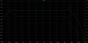
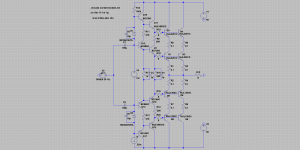
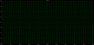
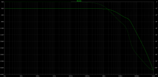
thank you, this was it however I had to increase C3,7 (on my circuit) from 22n to 220n, sims attached.
Not that bad for me.
N-Period=1
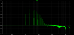
Fourier components of V(vout)
DC component:-0.000631128
Harmonic Frequency Fourier Normalized Phase Normalized
Number [Hz] Component Component [degree] Phase [deg]
1 1.000e+03 7.884e+00 1.000e+00 -0.01° 0.00°
2 2.000e+03 1.937e-03 2.457e-04 -89.04° -89.04°
3 3.000e+03 4.242e-04 5.380e-05 -8.43° -8.43°
4 4.000e+03 1.931e-04 2.449e-05 -87.98° -87.98°
5 5.000e+03 3.445e-04 4.369e-05 -1.22° -1.21°
6 6.000e+03 1.169e-05 1.482e-06 -82.96° -82.95°
7 7.000e+03 6.982e-05 8.856e-06 0.68° 0.69°
8 8.000e+03 5.218e-06 6.619e-07 87.23° 87.23°
9 9.000e+03 5.952e-06 7.550e-07 9.26° 9.26°
Total Harmonic Distortion: 0.025660%
Attachments
When you say large enough, what sort of size are you looking at? I have read large caps in a circuit of this type are risky as to what effect they would have on sound (Assuming I'm correctly understanding the term bridge cap to be otherwise known as a speed up cap).
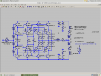
A reasonable value would probably be 5-10 times the total input capacitance of the FETs. I found in simulation 220nF was enough for 2 pairs of K1056/J162 (Cordell's models).
diamond
Hi Keane,
One more remark about a diamond style output stage. Years ago I've simmed syn08's YAP amp, which also uses this topology, and observed a new source of instability. With high and fast slewing output levels, the bias tends to decrease and, as you remarked, it even collapses in case of oscillation. BUT... a diminishing bias by itself may lead to oscillations, that is, under certain conditions (and of course depending on certain circuit details). It is caused by a too low bias of the driver and/or output stage, which in turn results in a lower fT. Hence the instability. So both topologies (EF and diamond) have their drawbacks and this is one more reason I prefer separate push-pull (totem pole) drivers.
> but I didn't want to add 2 more transistors
and I don't want to add 2 more transistors for the current sources, needed for a diamond OPS.")
Cheers, E.
[..]
Furthermore, it seems in high-slewrate designs EF drivers are a potentially huge mistake. If the amp bursts into oscillation, the drivers go into class B mode and act like a rectifier jacking up bias to only a few hundred simulated amps. Even if current limited to 7A or so, in a prototype this would be a huge issue, mandating a diamond driver stage. A diamond stage will collapse bias instead, and still retains indefinite transient drive ability if you use a cap to connect the emitters. A useful amp should never be in danger of oscillation, but this is not something I would want to deal with in a prototype. I could not find a way to keep a normal EF driver from throttling the bias.
[..]
Hi Keane,
One more remark about a diamond style output stage. Years ago I've simmed syn08's YAP amp, which also uses this topology, and observed a new source of instability. With high and fast slewing output levels, the bias tends to decrease and, as you remarked, it even collapses in case of oscillation. BUT... a diminishing bias by itself may lead to oscillations, that is, under certain conditions (and of course depending on certain circuit details). It is caused by a too low bias of the driver and/or output stage, which in turn results in a lower fT. Hence the instability. So both topologies (EF and diamond) have their drawbacks and this is one more reason I prefer separate push-pull (totem pole) drivers.
> but I didn't want to add 2 more transistors
and I don't want to add 2 more transistors for the current sources, needed for a diamond OPS.
Cheers, E.
Thanks for the information. I guess I should be saying "I don't want to add 6 more solder joints". Lol!
I have a way of doing it without needing current sources actually, that doesn't involve extra transistors. However I found great gains in the totem pole scheme, which in this case I think warrant the 2 extra transistors. The diamond configuration is still great though by modern standards, and would make a good simplified amp.
The bias collapsing can cause oscillation, but this is why snubbing has to be clever, and compensation has to be oblivious to capacitance. Large gate stoppers mean the compensation can't ignore the dynamic capacitances, which of course it can't track.
What I'm dealing with right now is the Ft doubling that occurs during crossover according to Cordell's models. BJTs seem to be lossy whereas FETs are very high-Q. As a result you end up with oodles of resonances and peaking at 10MHz no matter what. But I am trying to get away with 15R gate stoppers. Why not use larger stoppers? That doesn't really fix the problem, and actually tends to make it worse for a high-BW amp because it just makes them less predictable.
I actually have the prototype built and am testing things as I go along. I have not seen oscillation so far, but I can't say what my Tek 465B is missing.
A reasonable value would probably be 5-10 times the total input capacitance of the FETs. I found in simulation 220nF was enough for 2 pairs of K1056/J162 (Cordell's models).
thank you, keantoken. I think I'll allow for one of these caps in my amp project. Better to have the option.
Next question... What is the mechanism for the collapsing bias during clipping / oscillation in the diamond output stage. I have seen it happen in Ltspice. Is there anyway of stopping it?
Next question... What is the mechanism for the collapsing bias during clipping / oscillation in the diamond output stage. I have seen it happen in Ltspice. Is there anyway of stopping it?
Transistors only give current one way. If the VAS drives the OPS too hard, one of the drivers will turn off. Since it cannot sink any more current, the capacitance between the emitters absorbs the current and this leads to bias pumping or bias collapse depending on whether you use a diamond or EF driver stage. You can see the driver stage like a half-wave rectifier with the load between the emitters. An EF gives positive rectification and a diamond gives negative rectification.
As for stopping it, if the problem is oscillation then you need to stabilize your circuit. As far as other causes, it depends on the specific circuit.
Originally Posted by keantoken
but I can't say what my Tek 465B is missing.
Higher bandwith
All the best with your design, can't wait to see it
Transistors only give current one way. If the VAS drives the OPS too hard, one of the drivers will turn off. Since it cannot sink any more current, the capacitance between the emitters absorbs the current and this leads to bias pumping or bias collapse depending on whether you use a diamond or EF driver stage. You can see the driver stage like a half-wave rectifier with the load between the emitters. An EF gives positive rectification and a diamond gives negative rectification.
As for stopping it, if the problem is oscillation then you need to stabilize your circuit. As far as other causes, it depends on the specific circuit.
Thank you, makes sense to me now. Oscillation isn't a problem now for my design. It makes use of shunt compensation at the VAS input and VAS output. When you say about using compensation that is oblivious to capacitance would it be possible to elaborate a little.
Thank you for helping out a relative beginner.
You see this in most of the circuits Michael Kiwanuka has posted ... if you put some real loads on the output.BUT... a diminishing bias by itself may lead to oscillations, that is, under certain conditions (and of course depending on certain circuit details). It is caused by a too low bias of the driver and/or output stage, which in turn results in a lower fT. Hence the instability.
We await his book with bated breathe ... to see how or if he gets around this
- Home
- Amplifiers
- Solid State
- Bob Cordell's Power amplifier book