Hi Bob
Indeed your results may be somewhat different because of topology and compensation used.
My results were obtained through simulation of the regular blameless topology. If no-one posts the Self reference before Ill post it tommorrow. If I remember correctly it is in his fifth edition where he took actual measurements of this technique.
Thanks, manso.
I should add that I like the replica technique because it does not hang any components off of the LTP tail. Anything hanging there may degrade common mode rejection at high frequencies and add to EMI susceptibility.
Cheers,
Bob
One thing to consider is that bootstrapping with a significantly bandwidth-limited signal leads to negativ input capacitance of the bootstrapped transistor. Unless adressed, this may cause instability.
Samuel
Hi Samuel,
Good point. However, I always put 100 ohms in the emitter of each cascode device, even when not doing any driving of the cascode. Nevertheless, this whole stability thing is worth a closer look.
Cheers,
Bob
Not at all. Inductors are used as effective current sources in switch-mode circuits all the time, especially the ubiquitous clamped inductive load test circuit. What Bob said: Is 100% true.
Once current is set up in a large inductor it behaves a lot like a current source. You know, just how a very large capacitor that has been previously energised (aka "charged") behaves a lot like a voltage source.
Hi Harry,
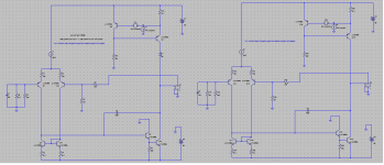
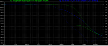
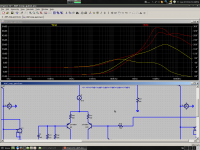
That this view is incorrect may be established by running a simulation of the loop gain of the amplified negative feedback current source with the very large inductor removed from the collector of the source transistor so that said source transistor is loaded exclusively by the output impedance of the transimpedance stage's transistor. The latter is then effectively an active current sink for the ANF current source. See figure below.
Now, if the large inductor (used in the circuit on the left to isolate the ANF current source from the rest of the circuit) behaved like a current source, as you and Bob contend, then the loop gain in both instances (with and without the inductor) would be virtually the same.
In fact the loop gain local to the ANF current source without the inductor to isolate it from the TIS current sink is over 40dB greater within the audio band than that obtained with the inductor in situ. (Blue trace: without inductor; green trace: with inductor).
This suggests that far from behaving like a current source, as you aver, the inductor in this case merely acts to isolate one circuit node from another at the frequencies of interest as Rosenstark indicates in his paper “Loop Gain Measurement in Feedback Amplifiers" Int. Journal of Electronics, Vol. 57, No.3., pp. 415-421, 1984 and in his book "Feedback Amplifier Principals".
From the figure below it is apparent that the true loop gain local to the ANF current source is obtained with its collector isolated from the rest of the circuit at the frequencies of interest by the large inductor.
Attachments
Last edited:
Hi Harry,
That this view is incorrect may be established by running a simulation of the loop gain of the amplified negative feedback current source with the very large inductor removed from the collector of the source transistor so that said source transistor is loaded exclusively by the output impedance of the transimpedance stage's transistor. The latter is then effectively an active current sink for the ANF current source. See figure below.
Now, if the large inductor (used in the circuit on the left to isolate the ANF current source from the rest of the circuit) behaved like a current source, as you and Bob contend, then the loop gain in both instances (with and without the inductor) would be virtually the same.
In fact the loop gain local to the ANF current source without the inductor to isolate it from the TIS current sink is over 40dB greater within the audio band than that obtained with the inductor in situ. (Blue trace: without inductor; green trace: with inductor).
This suggests that far from behaving like a current source, as you aver, the inductor in this case merely acts to isolate one circuit node from another at the frequencies of interest as Rosenstark indicates in his paper “Loop Gain Measurement in Feedback Amplifiers" Int. Journal of Electronics, Vol. 57, No.3., pp. 415-421, 1984 and in his book "Feedback Amplifier Principals".
From the figure below it is apparent that the true loop gain local to the ANF current source is obtained with its collector isolated from the rest of the circuit at the frequencies of interest by the large inductor.
Hi Mike,
You are finally beginning to get something that resembles the right answer, but you are drawing the wrong conclusion based on a wrong understanding of the VAS circuit in the closed loop amplifier and with the Miller compensation.
Your statement that the current source loop gains should be the same whether the inductor is in or out is wrong. The VAS node DOES NOT look like a current source for AC. It looks like a fairly low impedance because the feedbacks in the amplifier keep it that way. This allows the feedback current source to function normally. This is why your loop gain analysis came up with the larger loop gain number that all of the rest of us have been asserting all along.
Cheers,
Bob
Hi Harry,
That this view is incorrect
It is not a "view", it is fact.
Do you deny that a charged very large capacitor behaves like a voltage source? Very large inductors are the dual of very large capacitors. Very large inductors require a very large volt-second product to be applied in order to change the current flowing; very large capacitors require very large current-second product to be applied in order to change the voltage across them. Which of these facts do you deny?
When you run a frequency analysis in LTspice, the first step is the determination of a DC operating point; this allows all non-linear circuit elements to be replaced with linearised models at their respective operating points and for the initial voltage or current in energy storage elements (respectively capacitors and inductors) to be determined.
The DC operating point analysis of the circuit with the very large inductor will determine that a certain DC current is flowing through it. Do you deny this?
V=L * di/dt Do you deny this?
di = V * dt/L Do you deny this?
According to the equation above, if L is very large, this requires the V*dt product to be similarly large in order for the current to change a non-negligible amount. Do you deny this?
In the frequency analysis, an effectively infinitely small ac signal is used to analyse the circuit's frequency response. Do you deny this?
From where is the very large voltage required to change the inductor's current going to come?
Answer - it is not going to come from anywhere and the inductor is behaving like a current source.
A large inductor is not always the correct component to "isolate" one part of a circuit from another.
Last edited:
Your statement that the current source loop gains should be the same whether the inductor is in or out is wrong. The VAS node DOES NOT look like a current source for AC. It looks like a fairly low impedance because the feedbacks in the amplifier keep it that way. This allows the feedback current source to function normally. This is why your loop gain analysis came up with the larger loop gain number that all of the rest of us have been asserting all along.
Cheers,
Bob
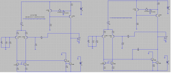
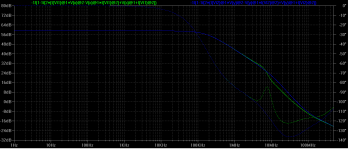
This was what I thought initially; viz. that because of minor loop feedback the TIS couldn't funtion as a current sink. I was wrong and so are you.
I established this fact by removing the miller compensation capacitor on the amplifier on the left and removing the inductor in both cases. If the minor loop feedback were to make a difference, then the loop gain local to the ANF current source would be radically different in both cases. It isn't. See below.
Attachments
Mike,
I'm not entirely sure why you even want to measure the current sources' loop gain when it's isolated from the rest of the circuit. Surely what matters is the stability of the loop when the circuit is operating normally, i.e. current source and TIS are not isolated from one another?
I'm not entirely sure why you even want to measure the current sources' loop gain when it's isolated from the rest of the circuit. Surely what matters is the stability of the loop when the circuit is operating normally, i.e. current source and TIS are not isolated from one another?
A large inductor is not always the correct component to "isolate" one part of a circuit from another.
Suffice it to say that it is used both in practice and in simulation to isolate circuit nodes from each other at the frequencies of interest by a great many luminaries in the field who would disagree with your averment.
Mike,
I'm not entirely sure why you even want to measure the current sources' loop gain when it's isolated from the rest of the circuit. Surely what matters is the stability of the loop when the circuit is operating normally, i.e. current source and TIS are not isolated from one another?
As you've noticed by now the loop gain of the ANF current source is highly dependent on its collector load.
Thus, the purpose of isolating it from extraneous circuitry is to establish its intrinsic loop gain.
Suffice it to say that it is used both in practice and in simulation to isolate circuit nodes from each other at the frequencies of interest by a great many luminaries in the field who would disagree with your averment.
No, it will not suffice to say that, because they use large inductors to isolate a voltage source (the output of a feedback amplifier) from a medium-impedance load (the input to the feedback network). They don't use the large inductor to isolate a current source from a low impedance load.
An inductor is not always the right component to use to isolate parts of a circuit from one another.
You have not provided any rebuttal of post #3465. Perhaps you are working on this. I hope in the process you realise that we are correct about the fact that very large inductors behave like current sources.
Thus, the purpose of isolating it from extraneous circuitry is to establish its intrinsic loop gain.
As I said, why care about that? What's important is stability of the loop in its actual real-life operating condition.
What's important is stability of the loop in its actual real-life operating condition.
I agree; that is vital. However Bob's urgument which I disputed was that the intrinsic loop gain of the ANF current source was much larger than I had demonstrated. He asserted that the source of the error in my simulation was the presence of the inductor. This is not true as I have demonstrated.
No, it will not suffice to say that, because they use large inductors to isolate a voltage source (the output of a feedback amplifier) from a medium-impedance load (the input to the feedback network). They don't use the large inductor to isolate a current source from a low impedance load.
On the contrary, the principal is to isolate one circuit node from another regardless of their relative impedances. You clearly haven't read Rosenstark exhaustively; I have.
Last edited:
You are finally beginning to get something that resembles the right answer, but you are drawing the wrong conclusion based on a wrong understanding of the VAS circuit in the closed loop amplifier and with the Miller compensation.
Maybe, or maybe not; but certainly a patronizing tone doesn't stimulate any constructive discussions.
Harry,
Read the following. Towards the end of the page you'll find the following sentence:
"Another PSpice method involves inserting a large inductor (Lins) in the amplifier’s feedback loop (Fig. 6). It opens the loop for the ac signal, but keeps it closed for dc."
Use PSpice To Verify Feedback Amplifier Stability | Analog content from Electronic Design
Additionally, see below:
http://www.spectrum-soft.com/news/winter2001/loopgain.shtm
Finally, Rosenstark's book:
http://web.njit.edu/~rosensta/books/Feed_Back_Amps.pdf
Last edited:
Harry,
Read the following. Towards the end of the page you'll find the following sentence:
"Another PSpice method involves inserting a large inductor (Lins) in the amplifier’s feedback loop (Fig. 6). It opens the loop for the ac signal, but keeps it closed for dc."
Use PSpice To Verify Feedback Amplifier Stability | Analog content from Electronic Design
Additionally, see below:
Plotting Loop Gain and Phase Margin - Winter 2001
I don't need to read these (some of them again), as I really do understand perfectly well the principle of inserting a very large inductor into a feedback loop for loop-gain simulation.
By inserting the very large inductor between the current source output and the TIS, you have made an effectively open circuit at the current source output at all frequencies apart from DC (you must agree with that because that's exactly what the sentence you quote above states). How is this showing the "intrinsic" behaviour of the current source?
Why even simulate the current source with all the other amplifier guff if you're going to isolate it? Why not just simulate it by itself? And in order to show off the "intrinsic" behaviour, surely it would be best to present it with the "kindest" load, which for a current source is a short circuit from DC to daylight (the dual of the "kindest" load for a voltage source being an open circuit from DC to daylight).
Thank you for posting this link.
This was what I thought initially; viz. that because of minor loop feedback the TIS couldn't funtion as a current sink. I was wrong and so are you.
I established this fact by removing the miller compensation capacitor on the amplifier on the left and removing the inductor in both cases. If the minor loop feedback were to make a difference, then the loop gain local to the ANF current source would be radically different in both cases. It isn't. See below.
Mike,
You are still not getting it right. There are TWO loops of negative feedback that both act to create a very finite impedance at the output of the VAS. You are ignoring the global loop.
You would better off at this point to honestly establish for yourself the truth by abandoning all of the complex mistake magnets in what you are doing and first do the simple sanity check with a feedback current source TOTALLY by itself with a reasonable resistive load to the rail or just conneted to the rail. THEN, once you have convinced yourself of that, you can go on and try to figure out why you are magnetically attracting so many mistakes in your present approach.
Cheers,
Bob
There are TWO loops of negative feedback that both act to create a very finite impedance at the output of the VAS. You are ignoring the global loop.
The major feedback loop has no impact, at least to a first order, on the output impedance of the TIS. You can confirm this by disabling the major loop by means of a large capacitor shunting the inverting input of the amplifier to ground or using a large inductor in series with the inverting input of the amplifier.
Further, Bob, I have also demonstrated that the minor loop has no effect on the loop gain of the ANF current source. Why do you find this so difficult to appreciate?

Tomorrow I'll do as you've asked; viz. run a sim of the loop gain of the current source with a resistive load.
The results with an without the miller cap are the same, because it is global feedback that reduces TIS Zout, not miller feedback, in order to prevent signals at the VAS output from causing error in the output.
Here is your simulation modified to actually show the TIS Zout, instead of assuming what it is. It only changes at RF, where it DOES make a difference as your plot in your post shows.
Here is your simulation modified to actually show the TIS Zout, instead of assuming what it is. It only changes at RF, where it DOES make a difference as your plot in your post shows.
Attachments
- Home
- Amplifiers
- Solid State
- Bob Cordell's Power amplifier book