Miller loop
Hi Olivier,
First, let's start with the VAS. In order to accurately simulate the loop gain you have to look at the voltage gain as well as the current gain. How to do that with MC is describe here: Simulating Loop Gain - Spring 1997 and here: Loop Gain
However, this method is a bit cumbersome, as you need an additional copy of the circuit. To avoid this extra copy, you can look if there is a suitable point to break the loop where only one the components (either voltage or current) is very large with respect to the other component.
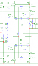
In this case there is such a point for the voltage component: between the emitter of Q19 (having a low impedance) and the base of Q23 (having a high impedance). Now we break the loop by inserting a huge inductor (L1), which blocks AC signals but preserves the DC operating point.
Via a large capacitor (C13) we inject a voltage into the base of Q23 and looks what happens at the emitter of Q19, which acts like an output.
Of course, we are not done yet, as there is one more VAS. So we inject the signal also into the base of Q26 via C14 and combine the output signal from Q20 to a common point (U) via C10. Needless to say that we also have to break the loop of the second VAS by means of L2 (fig. 1).
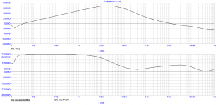
Now we simply look at the relationship between V(vin) and V(u) (fig. 2).
Knowing that this method is not accurate (and basically wrong), I've compared the results with Tian's method. Happily, the results were almost identical.
As the ULGF of your original circuit was pretty high, I've adjusted several components: The Miller and TMC caps are now 47pF resp. 220pF and lead lag compensation at the VAS inputs is 330pF in series with 15 Ohms.
Now the phase margin is 94 degrees at an ULGF of 11.5MHz, that is, simmed with above method as well with a Tian gain probe.
Regarding lead-lag compensation at the VAS output (as suggested by Walter) I prefer to put this additional compensation at the VAS input, as it does a better job of suppressing HF ingress (courtesy of Glen K.)
BTW, increasing the compensation caps has a price: more distortion! But what do you prefer: the lowest possible distortion or a more stable amp?
I would say, don't push this amp to the limits. Moreover, you don't know yet what will happen when you connect the final OPS to this front-end.
Cheers,
E.
PS1: I've also included a MC file (*.cir.txt)
PS2: The (small) phase dip at 400kHz is due to TMC)
...........
Hi Edmond,
Have a good beer. I am eager to learn more about assessing the loop properties. I didn't do any testing today so nor did I capacitively load the OPS. It is indeed better to analyse ad fundum the VAS properties instead of shooting at it with capacitive loading and other taunteries to see if it survives.
..............
Cheers !
Hi Olivier,
First, let's start with the VAS. In order to accurately simulate the loop gain you have to look at the voltage gain as well as the current gain. How to do that with MC is describe here: Simulating Loop Gain - Spring 1997 and here: Loop Gain
However, this method is a bit cumbersome, as you need an additional copy of the circuit. To avoid this extra copy, you can look if there is a suitable point to break the loop where only one the components (either voltage or current) is very large with respect to the other component.
In this case there is such a point for the voltage component: between the emitter of Q19 (having a low impedance) and the base of Q23 (having a high impedance). Now we break the loop by inserting a huge inductor (L1), which blocks AC signals but preserves the DC operating point.
Via a large capacitor (C13) we inject a voltage into the base of Q23 and looks what happens at the emitter of Q19, which acts like an output.
Of course, we are not done yet, as there is one more VAS. So we inject the signal also into the base of Q26 via C14 and combine the output signal from Q20 to a common point (U) via C10. Needless to say that we also have to break the loop of the second VAS by means of L2 (fig. 1).
Now we simply look at the relationship between V(vin) and V(u) (fig. 2).
Knowing that this method is not accurate (and basically wrong), I've compared the results with Tian's method. Happily, the results were almost identical.
As the ULGF of your original circuit was pretty high, I've adjusted several components: The Miller and TMC caps are now 47pF resp. 220pF and lead lag compensation at the VAS inputs is 330pF in series with 15 Ohms.
Now the phase margin is 94 degrees at an ULGF of 11.5MHz, that is, simmed with above method as well with a Tian gain probe.
Regarding lead-lag compensation at the VAS output (as suggested by Walter) I prefer to put this additional compensation at the VAS input, as it does a better job of suppressing HF ingress (courtesy of Glen K.)
BTW, increasing the compensation caps has a price: more distortion! But what do you prefer: the lowest possible distortion or a more stable amp?
I would say, don't push this amp to the limits. Moreover, you don't know yet what will happen when you connect the final OPS to this front-end.
Cheers,
E.
PS1: I've also included a MC file (*.cir.txt)
PS2: The (small) phase dip at 400kHz is due to TMC)
Attachments
Common mode contol loop
Hi Olivier,
Next, how to determine the gain and phase of the CMCL.
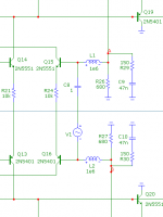
Again, better use a Tian gain probe, but also in this case we can keep it simple: break the loop by means of huge inductors and look at the voltage components.
Opposed to the Miller loop, now we have to inject a differential test signal at the base of Q15 respectively Q16, and look at the differential output voltage at node A and B (i.e. V(A,B)). Simple, isn't it?
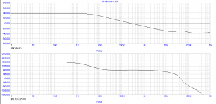
Notice that the ULGF (255kHz) of this circuit is lower than in my previous sim. This is because the lead-lag compensation at the VAS inputs, which has been changed, has a marked influence on the behaviour of the CMCL. Also notice that I've increased R29 & R30 from 100 to 150 Ohms for a slightly better phase margin.
For more details, just download (and run) the MC file.
Cheers,
E.
.................
No I did not determine UGFL for the CMCL (I am simply not capable of doing
.............
Thanks in advance !
Olivier
Hi Olivier,
Next, how to determine the gain and phase of the CMCL.
Again, better use a Tian gain probe, but also in this case we can keep it simple: break the loop by means of huge inductors and look at the voltage components.
Opposed to the Miller loop, now we have to inject a differential test signal at the base of Q15 respectively Q16, and look at the differential output voltage at node A and B (i.e. V(A,B)). Simple, isn't it?
Notice that the ULGF (255kHz) of this circuit is lower than in my previous sim. This is because the lead-lag compensation at the VAS inputs, which has been changed, has a marked influence on the behaviour of the CMCL. Also notice that I've increased R29 & R30 from 100 to 150 Ohms for a slightly better phase margin.
For more details, just download (and run) the MC file.
Cheers,
E.
Attachments
Last edited:
MC10
Hi Arthur,
I didn't notice much difference.
Cheers,
E
Hello Edmond
Apart from being able to do the Tian probe thing with MC10 is the package an improvement in terms of its convergence when compared to MC9.
Regards
Arthur
Hi Arthur,
I didn't notice much difference.
Cheers,
E
Moving target....
Hi Olivier,
Regarding post 2281 and the Miller caps, I've overlooked something: the emitter degen. resistors of the LTPs have been changed. I assumed they were still 47 Ohms and have, accordingly, adjust the Miller caps in order to keep the ULGF of the global NFB loop at a safe value. In the mean time, I discovered that they are now 120 Ohms. With these R's you can keep the Miller caps as shown in your posts 2258 and 2264, i.e. 33pF respectively 180pF. The TMC resistors however, I would increase them from 680 to 1000 Ohms.
Cheers,
E.
Hi Edmond,
I had no time yet to check your explanation of loop assessing but I will soon !
My FETS are LATERAL type MOSFETS 2SJ162/2SK1058 and have Vgs of just under 0,7V. Never tested under high current conditions however. Reading in Bob's book this might become seriously higher when heavy current flows.
Cheers,
Olivier
MicroCap files and the heritage of Randy Slone (RIP)
In post 2281 & 2281 I've put MC10 files by accident. With MC9 you can't open them. Sorry for the inconvenience. MC9 files (a few) can be found here: http://www.diyaudio.com/forums/soli...ogy-construction-troubles-38.html#post2787610 (a more appropriate thread for this topic).
Cheers,
E
In post 2281 & 2281 I've put MC10 files by accident. With MC9 you can't open them. Sorry for the inconvenience. MC9 files (a few) can be found here: http://www.diyaudio.com/forums/soli...ogy-construction-troubles-38.html#post2787610 (a more appropriate thread for this topic).
Cheers,
E
In post 2281 & 2281 I've put MC10 files by accident. With MC9 you can't open them. Sorry for the inconvenience. MC9 files (a few) can be found here: http://www.diyaudio.com/forums/soli...ogy-construction-troubles-38.html#post2787610 (a more appropriate thread for this topic).
Cheers,
E
Hi Edmond
In the thread you are linking to, you mention that you have tried different MOSFET models and none of them are "right". Why don't you use Bob's MOSFET models?
(Bob's models are of 2SJ162 and 2SK1056 not 2SK1058)
Cheers
Stein
Hi Stein,
I wasn't aware of the models from Bob. Where to get them, on his website?
Cheers,
E.
Hi Edmond
Yes, In the Cordell models file. Cordell models.
Cheers
Stein
Attachments
Hi Stein,
MC complains about these models. Are they written in LTSpice format?
Anyway, thanks for the effort.
Cheers,
E.
Hi Edmond
As Antonio is saying, you have to delete the mfg= to make Bob's models workable in Cadence or MC. I had to do that with all of Bob's models.
Cheers
Stein
Hi Antonio & Stein,
These are the models (no mfg=...):
* 2SJ162C VDMOS copyright Cordell Audio December 6, 2010
.model 2SJ162C VDMOS(pchan Vto=-0.08 Kp=0.6 Lambda=0.1 Rs=0.55 Rd=0.1 Rds=1e7 Cgdmax=215p Cgdmin=10p a=0.25 Cgs=900p Cjo=1200p m=0.7 VJ=2.5 IS=4.0E-06 N=2.4)
*
* 2SK1056C VDMOS copyright Cordell Audio December 6, 2010
.model 2SK1056C VDMOS(nchan Vto=0.02 Kp=0.85 Lambda=0.02 Rs=0.62 Rd=0.1 Rds=1e7 Cgdmax=100p Cgdmin=5p a=0.25 Cgs=600p Cjo=1080p m=0.7 VJ=2.5 IS=4.0E-06 N=2.4)
Clearly a proprietary LT format. Not compatible with standard spice.
BTW, WTF 'copyright Cordell Audio'? Has Bob extracted all these parameters?
Cheers,
E.
These are the models (no mfg=...
):* 2SJ162C VDMOS copyright Cordell Audio December 6, 2010
.model 2SJ162C VDMOS(pchan Vto=-0.08 Kp=0.6 Lambda=0.1 Rs=0.55 Rd=0.1 Rds=1e7 Cgdmax=215p Cgdmin=10p a=0.25 Cgs=900p Cjo=1200p m=0.7 VJ=2.5 IS=4.0E-06 N=2.4)
*
* 2SK1056C VDMOS copyright Cordell Audio December 6, 2010
.model 2SK1056C VDMOS(nchan Vto=0.02 Kp=0.85 Lambda=0.02 Rs=0.62 Rd=0.1 Rds=1e7 Cgdmax=100p Cgdmin=5p a=0.25 Cgs=600p Cjo=1080p m=0.7 VJ=2.5 IS=4.0E-06 N=2.4)
Clearly a proprietary LT format. Not compatible with standard spice.
BTW, WTF 'copyright Cordell Audio'? Has Bob extracted all these parameters?
Cheers,
E.
Hi Antonio & Stein,
These are the models (no mfg=...
* 2SJ162C VDMOS copyright Cordell Audio December 6, 2010
.model 2SJ162C VDMOS(pchan Vto=-0.08 Kp=0.6 Lambda=0.1 Rs=0.55 Rd=0.1 Rds=1e7 Cgdmax=215p Cgdmin=10p a=0.25 Cgs=900p Cjo=1200p m=0.7 VJ=2.5 IS=4.0E-06 N=2.4)
*
* 2SK1056C VDMOS copyright Cordell Audio December 6, 2010
.model 2SK1056C VDMOS(nchan Vto=0.02 Kp=0.85 Lambda=0.02 Rs=0.62 Rd=0.1 Rds=1e7 Cgdmax=100p Cgdmin=5p a=0.25 Cgs=600p Cjo=1080p m=0.7 VJ=2.5 IS=4.0E-06 N=2.4)
Clearly a proprietary LT format. Not compatible with standard spice.
BTW, WTF 'copyright Cordell Audio'? Has Bob extracted all these parameters?
Cheers,
E.
Hi Edmond
You have to replace VDMOS in the model with NMOS or PMOS
like this:
.model 2SK1056C NMOS(nchan Vto=0.02 Kp=0.85 Lambda=0.02 Rs=0.62 Rd=0.1 Rds=1e7 Cgdmax=100p Cgdmin=5p a=0.25 Cgs=600p Cjo=1080p m=0.7 VJ=2.5 IS=4.0E-06 N=2.4)
"BTW, WTF 'copyright Cordell Audio'? Has Bob extracted all these parameters?
"I'm confused as well, Bob claimed somewhere that he had spent a lot of time measuring a lot of transistors to make his models.
Cheers
Stein
models
Hi Stein,
Also the text nchan or pchan has to be removed. Nevertheless I got warnings about unknown parameters:
CGDMAX, CGDMIN, A CGS, CJO, M and VJ. As a result, capacitances are not modeled at all. I wish I could buy such MOSFETs.
Happily, here I found models that do work: http://www.diyaudio.com/forums/parts/3230-p-spice-models-4-2sk1058-2sj162.html#post998418 , that is, I don't get warnings.
That would have been a huge job. Anyhow, Bob, chapeau !
Cheers,
E.
Hi Edmond
You have to replace VDMOS in the model with NMOS or PMOS
like this:
.model 2SK1056C NMOS(nchan Vto=0.02 Kp=0.85 Lambda=0.02 Rs=0.62 Rd=0.1 Rds=1e7 Cgdmax=100p Cgdmin=5p a=0.25 Cgs=600p Cjo=1080p m=0.7 VJ=2.5 IS=4.0E-06 N=2.4)
Hi Stein,
Also the text nchan or pchan has to be removed. Nevertheless I got warnings about unknown parameters:
CGDMAX, CGDMIN, A CGS, CJO, M and VJ. As a result, capacitances are not modeled at all. I wish I could buy such MOSFETs.
Happily, here I found models that do work: http://www.diyaudio.com/forums/parts/3230-p-spice-models-4-2sk1058-2sj162.html#post998418 , that is, I don't get warnings.
I'm confused as well, Bob claimed somewhere that he had spent a lot of time measuring a lot of transistors to make his models.
Cheers
Stein
That would have been a huge job. Anyhow, Bob, chapeau !
Cheers,
E.
Hi Edmond
You have to replace VDMOS in the model with NMOS or PMOS
like this:
.model 2SK1056C NMOS(nchan Vto=0.02 Kp=0.85 Lambda=0.02 Rs=0.62 Rd=0.1 Rds=1e7 Cgdmax=100p Cgdmin=5p a=0.25 Cgs=600p Cjo=1080p m=0.7 VJ=2.5 IS=4.0E-06 N=2.4)
"BTW, WTF 'copyright Cordell Audio'? Has Bob extracted all these parameters?
I'm confused as well, Bob claimed somewhere that he had spent a lot of time measuring a lot of transistors to make his models.
Cheers
Stein
Hi Stein,
First of all, let me apologize to everyone here for putting the mfg= into my model files. I did not realize that it causes problems with other simulators.
With regard to my set of models, every model was created by hand, and a sample of every device was actually measured by me. This did indeed take an excrutiatingly long time. In general, I used the techniques that I described in my book. Having said that, not all parameters in each model were derived from measurements. For some parameters, I fitted the models to information in the datasheets, where that information was reasonable. Examples would be some parameters like Ccb and ft. For each device, I also used one or more manufacturer's SPICE models as a starting point. If some of the more obsure parameters looked reasonable, I used that value or a similar value.
Cheers,
Bob
Bob,
I , for one, admire and commend your approach and your decision to include the LTSpice-specific parameters such as "mfg=", "Vceo=", etc.
Questions of compatibility and library portability deserve a serious answer, not a cursory dismissal. In this case, Mike Engelhardt (the LTSpice author & architect) has chosen to "extend" the standard SPICE syntax, now roughly 40 years old and created for use in a computing environment that is barely recognizable from today's world. He is not unique in this regard: the encrypted models of HSPICE, and Multisim's method of mapping the nodes of a SPICE model to the pins of a schematic symbol come to mind. In my mind, making an LTSpice ".model" statement (containing the LTSpice-unique parameters) portable to other simulators is a very straightforward, and rather obvious effort. It requires only a very basic text-editor - in many cases adding a semicolon (introduced, as I recall, by PSPICE as the delimiting symbol for in-line comments) is all that's needed.
I think there's value in retaining the "mfg=" information. It's not just the fact that, as one of Edsel Murphy's corollaries states, "Interchangeable parts won't.". This Forum, of all places, appreciates that there are often subtle differences among interchangeable parts. Knowing the origins of a model's parameter values is at least a first step toward understanding those differences.
Bob, thanks for making the effort to develop those models and share the results. At least we know your methodology. In most cases you simply receive a model with no hints as to whether it was developed from purely theoretical considerations; from published (or perhaps unpublished) Data Sheet values; from measurements on a batch of components; or from measurements across several batches. You don't know if the model is intended to represent "typical" performance, or "worst-case" behavior, or a mixture. If the model was verified against physical measurements you don't know what operating conditions or applications were tightly controlled and which were allowed to simply fall "in the ballpark". With Bob Cordell's name on his work we at least know where to start looking for answers to these questions.
Dale
- Home
- Amplifiers
- Solid State
- Bob Cordell's Power amplifier book