Plus M7 and M8 of the Exclusive series, the M8 is a pimped M7, both marvellous sounding amps. (see M7 schematics at eserviceinfo)
from the schematics I can see that m7 was designed according to rules to minimalise memory distortion , maybe really memdist is the key for good sound from ss?
Hi Pete,
I applaud OS for his interest in the diamond buffer triple output stage and am humbled by his kind words for my discussion of it in the book. It really doesn't matter who invented what, and I certainly did not invent the diamond buffer. In fact, we first used it in op amps in the 1970's at Bell Labs when we developed the junction-isolated complementary BJT process for ICs.
What's important is that a good circuit gets explained and popularized. I also cringe a bit when a properly executed version of the old Linn circuit is referred to as the Blameless.
It is not a great technical leap to put a diamond buffer in front of a pair of output transistors and arrive at a nice Triple. I am, however, unaware of specific commercial power amplifiers that use this circuit. I'd like to reference these in the next edition of my book. Can you provide me those examples?
Thanks!
Bob
Yes I agree and appreciate your work and your book is fine as it stands, but it is also interesting and educational to provide a bit about the history behind these ideas. I know, there is only so much room in such a book. I seem to remember seeing your diamond configuration before but I might just be thinking of the LH0002, or actually a design on here, perhaps by jcx, not sure. There was the Marantz 300DC but it was not as clever with the low Vce. I seem to remember Sansui and DB systems also doing some innovative design but not sure if it involved the output diamond. I've not looked back at those old designs in a very long time.
Nelson also suggested a diamond for a line stage buffer many years ago.
It is basically a complementary Baxandall Super Pair for the pre-driver and driver as I see it:
http://www.diyaudio.com/forums/solid-state/25172-baxandall-super-pair.html
There have been long threads about stability issues with Baxandall Super Pairs, have you built it? I think older parts with higher internal Rbb will be less prone to oscillation.
Not exactly the same, but have you seen Andy's work on CFP stability analysis here:
Input stage distortion of Blameless amp and compensation of CFP
Last edited:
Baxandall Super pair is also discussed here:
http://www.diyaudio.com/forums/solid-state/166306-origins-baxandall-super-pair.html
Here in reply #2, but I've not had a chance to read them carefully:
Cascodes
http://www.diyaudio.com/forums/solid-state/166306-origins-baxandall-super-pair.html
Here in reply #2, but I've not had a chance to read them carefully:
Cascodes
Memory distortion is hardly the key, just one of a large number of keys. How is it minimized?
cfp input, cascoded vas
I tried the super pair (koda) for a VAS. It worked well , a little harder to compensate , but ended up like a standard Lin topology ... sound and performance wise.
I'm now back to my Hawksford cascode binge. I could not find much reference to it in Bob's book. Combining chapters 3.6 (cascoded Vas) ,7.4 (unipolar IPS/push-pull VAS) , and 10.4 (OP stages - DBT) I've come up with a real good DIY amp.
In the book , I also could not find much on CFP input stages besides the cascomp in ch 25.2. I've noticed superior THD and linearity in simulation and it actually works in real life. Combining this with the cascoded push-pull VAS (luxman like) and the DBT , I've achieved 3-10ppm 40v p-p 1k-20k without TMC "tricks". I actually built this before but with a EF2 - not too bad at low levels but "non-engaging" at high levels. The triple makes all the difference.
The IPS/voltage stage is (below 1) , and book's "DBT" is (below 2).
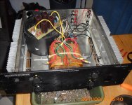
This is the my first amp that will use this book as a "filter" , the reference to the Holman amp (7.4) was a unexpected bonus, (ps-the holman does not have the cascode as level shifter and uses a standard fixed bias-zener VAS cascode). (below 3) is the testbed for the new contraption.
The trafo is a R-core ... a ?? It is said both windings of a R-core cancel each others field out. If both windings have primary and secondary and one uses them individually for each channel and loads one amp down (loading the secondary of one winding down as well) will this "unbalance" the trafo (the R-core) ?


So he said ....
OS
I'm now back to my Hawksford cascode binge. I could not find much reference to it in Bob's book. Combining chapters 3.6 (cascoded Vas) ,7.4 (unipolar IPS/push-pull VAS) , and 10.4 (OP stages - DBT) I've come up with a real good DIY amp.
In the book , I also could not find much on CFP input stages besides the cascomp in ch 25.2. I've noticed superior THD and linearity in simulation and it actually works in real life. Combining this with the cascoded push-pull VAS (luxman like) and the DBT , I've achieved 3-10ppm 40v p-p 1k-20k without TMC "tricks". I actually built this before but with a EF2 - not too bad at low levels but "non-engaging" at high levels. The triple makes all the difference.
The IPS/voltage stage is (below 1) , and book's "DBT" is (below 2).
This is the my first amp that will use this book as a "filter" , the reference to the Holman amp (7.4) was a unexpected bonus, (ps-the holman does not have the cascode as level shifter and uses a standard fixed bias-zener VAS cascode). (below 3) is the testbed for the new contraption.
The trafo is a R-core ... a ?? It is said both windings of a R-core cancel each others field out. If both windings have primary and secondary and one uses them individually for each channel and loads one amp down (loading the secondary of one winding down as well) will this "unbalance" the trafo (the R-core) ?
cfp input, cascoded vas
So he said ....
OS
Attachments
16 ppm @ 102v p-p thd20
(below) is "ultra nice" (simulation only) at mega voltage swings. For this level of simplicity ... quite the deal. Sound wise , the real thing reflects this performance (spine chillin'). Eliminating (or greatly reducing) early effect/memory distortion makes this amp " lock on " to ultra low THD regardless of frequency / amplitude or even load (2R is the load at 100v p-p). Thd is mostly H2 and 3 (-115db). PPM will go only to 20 ... right at clipping (107 Vp-p).
I KNOW the real thing most likely will not do quite as well, but it sounds "golden" (better than my previous creations). I'm only running this amp off of my B._S (40-0-40vdc OEM) power supply now .. can't wait to hook it to the ALTEC PS.
OS
(below) is "ultra nice" (simulation only) at mega voltage swings. For this level of simplicity ... quite the deal.
Sound wise , the real thing reflects this performance (spine chillin'). Eliminating (or greatly reducing) early effect/memory distortion makes this amp " lock on " to ultra low THD regardless of frequency / amplitude or even load (2R is the load at 100v p-p). Thd is mostly H2 and 3 (-115db). PPM will go only to 20 ... right at clipping (107 Vp-p).I KNOW the real thing most likely will not do quite as well, but it sounds "golden" (better than my previous creations). I'm only running this amp off of my B._S (40-0-40vdc OEM) power supply now .. can't wait to hook it to the ALTEC PS.
OS
Attachments
can't wait to hook it to the ALTEC PS.
lucky!
I am fixing old JVC A-K11
but will rebuild it into your way!
Plus M7 and M8 of the Exclusive series, the M8 is a pimped M7, both marvellous sounding amps. (see M7 schematics at eserviceinfo)
Jacco, a link to that schematic please.
Jacco, a link to that schematic please.
please accept from me:
Pioneer M7 Exclusive Service Manual free download,schematics,datasheets,eeprom bins,pcb,repair info for test equipment and electronics
padamiecki,
certainly, distortions including memory distortion are reduced, but that is not a specific, exclusive way to address memory distortion. Memory distortion is just a part of a complex distortion pattern.
WuYit
if you was looking for sophisticated discussion about memdist - what a pitty - all I know is that a single ss device (a transistor) can remember for some time the current that came through it and in that way caused distortions.
A complex of the devices which are working at constant current or voltage is better, but the best is when constant power through them is assured, which is similar like for electron tube, which sounds for me the best.
There are many things to consider to get good amp,
but for me cfp input + cascoded vas = beware, the sound might be good.
Last edited:
Bob I think you are only going to find 2, maybe 3 and all by the same manufacturer, namely Pioneer. The circuit was used by them in around 1983-1988 in their exclusive series of amps. One of the models is the M6.
Hi homemodder,
Thanks for this heads-up. Pioneer did indeed make some good stuff.
Cheers,
Bob
It is basically a complementary Baxandall Super Pair for the pre-driver and driver as I see it:
http://www.diyaudio.com/forums/solid-state/25172-baxandall-super-pair.html
There have been long threads about stability issues with Baxandall Super Pairs, have you built it? I think older parts with higher internal Rbb will be less prone to oscillation.
Not exactly the same, but have you seen Andy's work on CFP stability analysis here:
Input stage distortion of Blameless amp and compensation of CFP
Hi Pete,
I have not used a Baxandall super pair as shown in the link you provided, but I have largely used it in an emitter-follower kind of configuration, which, when done in a complementary way, becomes somewhat of a diamond buffer where the collectors of the first pair are bootstrapped to the output node instead of connected to the rails. I used such an arrangement in the amplifiers I designed for my Arthena active loudspeaker systems, where I used BJT folded emitter followers to drive output MOSFETs (described on my web site at CordellAudio.com - Home). The collectors of the folded emitter followers were connected to the output node. That is also when I used the Flying Catch Diodes for the first time.
I haven't seen Andy's work on the CFP stability yet.
Cheers,
Bob
I tried the super pair (koda) for a VAS. It worked well , a little harder to compensate , but ended up like a standard Lin topology ... sound and performance wise.
I'm now back to my Hawksford cascode binge. I could not find much reference to it in Bob's book. Combining chapters 3.6 (cascoded Vas) ,7.4 (unipolar IPS/push-pull VAS) , and 10.4 (OP stages - DBT) I've come up with a real good DIY amp.
In the book , I also could not find much on CFP input stages besides the cascomp in ch 25.2. I've noticed superior THD and linearity in simulation and it actually works in real life. Combining this with the cascoded push-pull VAS (luxman like) and the DBT , I've achieved 3-10ppm 40v p-p 1k-20k without TMC "tricks". I actually built this before but with a EF2 - not too bad at low levels but "non-engaging" at high levels. The triple makes all the difference.
The IPS/voltage stage is (below 1) , and book's "DBT" is (below 2).
This is the my first amp that will use this book as a "filter" , the reference to the Holman amp (7.4) was a unexpected bonus, (ps-the holman does not have the cascode as level shifter and uses a standard fixed bias-zener VAS cascode). (below 3) is the testbed for the new contraption.
The trafo is a R-core ... a ?? It is said both windings of a R-core cancel each others field out. If both windings have primary and secondary and one uses them individually for each channel and loads one amp down (loading the secondary of one winding down as well) will this "unbalance" the trafo (the R-core) ?
So he said ....
OS
Hi OS,
These are great suggestions for better coverage when I do the second edition of my book. I encourage everyone to bring these sorts of things to my attention. It is much appreciated.
Cheers,
Bob
Hi OS,
These are great suggestions for better coverage when I do the second edition of my book. I encourage everyone to bring these sorts of things to my attention. It is much appreciated.
Cheers,
Bob
I would never tell someone how to write a book
, but look to the Japanese OEM's for some of the best topologies. The OEM's are not dumb (economically driven sometimes) in their design choices. For high MTBF and cheap STK module offerings they use the standard 3-stage LIN topology with varying degrees of refinement. For a real "listening amp" (mid to audiophile) Push -pull VAS's and triple OP's are the rule. The pioneer amps are quite revered in their MTBF and sound. Thank you , padamiecki .. for the M7 schema. It looks different than the "DBT", more like the voltage follower DB current amp (my nakamitchi 620 example). This means that Bob's "DBT" is unique to the book , no exact commercial equivalent. More "DIY" friendly as well , it can be used with any popular IPS/VAS combo plus is quite easy to thermally stabilize. I would say it's ultimate form would be with the Thermaltrack's , 2 of the internal diodes controlling the Vbe (like the leach). Njl3281/1302 is out of the reach of some hobbyist's ... 5.41 X 12 = $65usd for a 2 X 150W amps. Same power with the NJW's is only 1.80 X 12 = $21usd for the same 150W !
OS

Hi Pete,
I have not used a Baxandall super pair as shown in the link you provided, but I have largely used it in an emitter-follower kind of configuration, which, when done in a complementary way, becomes somewhat of a diamond buffer where the collectors of the first pair are bootstrapped to the output node instead of connected to the rails. I used such an arrangement in the amplifiers I designed for my Arthena active loudspeaker systems, where I used BJT folded emitter followers to drive output MOSFETs (described on my web site at CordellAudio.com - Home). The collectors of the folded emitter followers were connected to the output node. That is also when I used the Flying Catch Diodes for the first time.
I haven't seen Andy's work on the CFP stability yet.
Cheers,
Bob
I've not looked at the details for the Baxandall Super Pair but what I meant was simply the connection of Q1 and Q2. The example I gave used the pair as a common emitter amp whereas your predriver-driver is a common collector connection. Still the predriver and driver are wired roughly in the Baxandall Super Pair way as I see it. Most view the Baxandall Super Pair as an alternative connection to a Darlington pair, from what I've seen, and of course either can be used in common emitter or common collector configurations.
- Home
- Amplifiers
- Solid State
- Bob Cordell's Power amplifier book