Off-course, anyone is free to comment on the clamps, but on the whole circuit too !!!
For now simulation shows 1.6ppm THD20 at full swing - not loaded (only vas & ips, no ops!).
Quite complex. No?
Is that complexity to have low distorsion at 20kHz? But your figure is without OPS. So...
thd
Hi Macload,
I am aware of the relativity of THD figures, especially if it is w/o OPS. Maybe a bit surprisingly, I am not specificaly searching for THD world records, far from it. So why the the complexity? Well because I like the Mirror Image topologies with current mirror loaded LTP's combined with a Cascoded darlington VAS. Off-course there is the VAS Iq issue, and I see it as a challenge to solve it (even if I have not invented the solution for it - my capacities are too limited for that). As a matter of fact I started out with this circuit reading Randy Slone's book. I lost much time with, but I learned a lot of things while burning down too many transistors... So I have a strong will to make it work...
My concern for the moment are thos clamp diodes in the VAS and in the IPS. I have seen so many different options ... is this a good one?
Cheers
Olivier
Hi Bob,
Thank you for your comments.
I wanted to keep drain - source valtage constant. Luxman amp did it simple with resistor devider. Roender is using something similar in his one stage amp.
I don't understand what you mean by using emitter follower. How to connect it to feedback signal? If you could put some diagram here, as I did not find, how to best bias a cascode, in your book.
C7 is suggested by Samuel Groner in his comment on D.Self. It enhace slew rate. And indeed in my simulation it increased dow slope from cca 70V/us to cca 90V/us. http://www.diyaudio.com/forums/soli...r-amplifier-design-handbook-douglas-self.html
R42 is used to adjust the bias. I used your suggestion for ThermalTrak from the tread http://www.diyaudio.com/forums/soli...n-thermal-trak-transistors-2.html#post1265193
I included a new LTSpice with simpler cascode bias, TTP tail current of 6mA.
Damir
Hi Damir,
I guess the use of C7 is a way of getting the VAS to act in a push-pull sort of way at HF without going to the trouble of a complementary VAS and complementary VAS drive arrangement. It may increase the slew rate, but I just would not go there. Whether it increases slew rate depends on where the slew rate limitation in the amplifier without C7 is occurring.
The emitter follower I was mentioning would have its base connected to the tail of the LTP and its emitter would be used to drive the common mode signal to the bases of the cascode. This buffers the tail from having to be loaded and to have the extra bias current injected.
Cheers,
Bob'
Hi Bob,
I hope I understand how to do that. Something like this?
regards Damir
Attachments
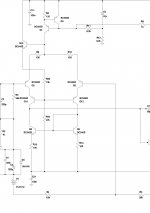
Hi Bob,
Reading about Bakerclamps in your book I implemented some in the joined circuit. Are these well placed?
For information : OPS is still not implemented nor is the bias circuit.
Off-course, anyone is free to comment on the clamps, but on the whole circuit too !!!
For now simulation shows 1.6ppm THD20 at full swing - not loaded (only vas & ips, no ops!).
Cheers,
Olivier
Hi Olivier,
You've got a lot going on in this circuit. It looks like you are using clamp diodes that effectively feed back from the output of the VAS to the input of the VAS to keep the VAS out of saturation. This is not the usual use of Baker clamps in a power amplifier. The usual approach is much simpler, and was used, for example, in Tom Holman's APT-1. The clamp diodes go from the output of the VAS to a fixed voltage reference, preventing the VAS output from going more than a diode drop beyond the reference. The arrangement assumes a current-limited VAS.
Cheers,
Bob
Hi Bob,
I hope I understand how to do that. Something like this?
regards Damir
Hi Damir,
Yes, but you may want to replace R26 with a zener diode. As shown, it looks like there will be attenuation of the common-mode signal before it reaches the bases of the cascodes.
Cheers,
Bob
Bought my copy today at lunch. Nerdbooks.com in Richardson, TX.
Weird place, four large dogs follow you around. Then you have to
buy online from a Mac terminal, won't take cash. But also did not
have to pay shipping...
Also bought a book by Douglas Self right next to Cordell's. Couldn't
find Morgan Jones Valve Amplifiers. But they said they could get it.
Weird place, four large dogs follow you around. Then you have to
buy online from a Mac terminal, won't take cash. But also did not
have to pay shipping...
Also bought a book by Douglas Self right next to Cordell's. Couldn't
find Morgan Jones Valve Amplifiers. But they said they could get it.
Bought my copy today at lunch. Nerdbooks.com in Richardson, TX.
Weird place, four large dogs follow you around. Then you have to
buy online from a Mac terminal, won't take cash. But also did not
have to pay shipping...
Also bought a book by Douglas Self right next to Cordell's. Couldn't
find Morgan Jones Valve Amplifiers. But they said they could get it.
Hi kenpeter,
Thanks for buying my book and I hope you enjoy it.
I recently bought Valve Amplifiers by Morgan Jones from Amazon and I have given the whole thing a first pass look. I really think it is a good book.
Cheers,
Bob
The two things that drew me to the book were EKV models and KK.
But there is wayy more other good stuff here than I was expecting.
I am trying to understand how to hybrid model the IRFP240/9240?
Gather would have to be a .subckt, [CTRL+RightClick] and change
prefix field from MN or MP to X. Would you be OK with discussing
specific book given models outside the book?
The two things that drew me to the book were EKV models and KK.
But there is wayy more other good stuff here than I was expecting.
I am trying to understand how to hybrid model the IRFP240/9240?
Gather would have to be a .subckt, [CTRL+RightClick] and change
prefix field from MN or MP to X. Would you be OK with discussing
specific book given models outside the book?
Hi kenpeter,
Yes, I would be happy to discuss models, but I have to be careful what I promise because models can be a real time sink.
I'm still trying to finish up the new group of model updates I will be posting on my website. Almost every time I look at modeling I get angry with the manufacturers because their models are so awful. Look at the MJE340/350 spec sheet - they don't even quote ft, much less provide a graph of it.
Cheers,
Bob
Where is everyone?
Hi Olivier,
I've been a bit remiss lately in keeping the thread going and I apologize for that. I've been doing some traveling (some to promote the book), but also working very hard to finish up a bunch of new material that I want to put up on my web page in support of the book. Much of the effort has concerned the finishing up up more and refined transistor SPICE models. Noise measurement work for the numerous transistors and translating that into SPICE model numbers took quite a bit of time.
I just got back last night from the Midwest Audio Engineering Summit at Webster University in St. Louis where I gave a lecture on power amplifier design. It was a nice experience to interact with so many enthusiastic students who are going into audio engineering. BTW, this more means the context of mixing and producing recorded and live sound than electrical engineering. It was also very nice interacting with many of the other speakers, who included many very accomplished engineers and producers in the audio entertainment business.
If you have any topics you'd like to discuss or questions you have, I'm here to answer them.
Cheers,
Bob
Hi kenpeter,
I'm still trying to finish up the new group of model updates I will be posting on my website. Almost every time I look at modeling I get angry with the manufacturers because their models are so awful. Look at the MJE340/350 spec sheet - they don't even quote ft, much less provide a graph of it.
Cheers,
Bob
I have some older Motorola data books that also list the MJE341/344 which are lower voltage versions but they provide more data: Cob=15pF, Ft = 15MHz at 50 mA 10V.
I have some older Motorola data books that also list the MJE341/344 which are lower voltage versions but they provide more data: Cob=15pF, Ft = 15MHz at 50 mA 10V.
Hi Pete,
Thanks for this info. About two weeks ago I actually measured some MJE340 and 350 transistors for ft out of desperation. I was very surprized to get 18 MHz for the NPN MJE 340 but 30 MHz for the PNP MJE350, both at 20mA, 10V. As you know, PNP transistors are more often slower than the complementary NPN device.
Cheers,
Bob
Interesting about the MJE's
 My EX uses them correctly , I see (PNP active , NPN CCS). Everyone makes fun of these classic devices , but I have found they work excellent as a VAS device , even with higher Cob/lower Ft. Not the case with 1381/3503 or 992/1845 pairs ... nearly identical Ft - different manufacturing process.
 OS
my understanding was that hgiher electron mobility in N doped Si gave PNP an advantage in speed, noise from lower r_bb, r_x base resistance
holds for driver sized Q, maybe large output Q design has other tradeoffs?
Hi jcx,
I've just always assumed PNPs were slower, and most whose specs I've seen appear to be smaller, including small-signal devices. I'm pretty sure that's been my experience with linear IC transistors built in complementary processes as well. It would seem that the N-type base of a PNP would help make it faster due to higher mobility in the base, but there may be other factors at work that turn the tables. I have, however, usually seen lower rb in PNP devices.
Cheers,
Bob
Hi Pete,
Thanks for this info. About two weeks ago I actually measured some MJE340 and 350 transistors for ft out of desperation. I was very surprized to get 18 MHz for the NPN MJE 340 but 30 MHz for the PNP MJE350, both at 20mA, 10V. As you know, PNP transistors are more often slower than the complementary NPN device.
Cheers,
Bob
That is pretty good agreement. Did you use the method described in
MIL-M-38510/108A page 12?
http://www.dscc.dla.mil/Downloads/MilSpec/Docs/MIL-M-38510/mil38510ss108.pdf
That is done at 100 MHz, did you measure at 1 or 10 MHz, or ... ?
That is pretty good agreement. Did you use the method described in
MIL-M-38510/108A page 12?
http://www.dscc.dla.mil/Downloads/MilSpec/Docs/MIL-M-38510/mil38510ss108.pdf
That is done at 100 MHz, did you measure at 1 or 10 MHz, or ... ?
Hi Pete,
I measured AC beta at 500kHz, 1MHz and 2 MHz, all at both 1mA and 10mA. This is similar to the method described, except for the measurement frequency. Basically, I biased up the transistor with a 100-ohm load and fed a voltage from a test oscillator through a high resistance into the base. I used an HP652 test oscillator and an HP 400EL AC voltmeter. So basically I put in a known AC current and inferred the AC collector current by looking at the AC voltage at the collector.
Cheers,
Bob
- Home
- Amplifiers
- Solid State
- Bob Cordell's Power amplifier book