I really hope to avoid math but the wye-delta transformation of the TPC, TMC network does seem promising for some insight when interpreting the mixed feedback loop of VAS, OP in TMC - as long as we can deal with FNDR elements in feedback loops
I haven’t been able to install MathCad 11 (the only version to use, the last with the Maple Symbolic engine) on my Vista machine so I may be slow to fire up the old offline computer with the lousy monitor… that would require moving from the only comfy chair in the house
They use MuPAD now, I have 11 tied to an old machine with dead DVD and CD (lost all the docs and receipt of course). Is MuPAD that bad?
4times the LTP tail current requires 4times the value of compensation capacitance !
Is this in the book?
I intended to re-read many chapters. Looks like compensation chapters must be the first.
Hi Andrew,
Yes, that is correct if you keep the relative degeneration factor the same; that means that the 470 ohm resistors would go down to 118 and overall gm of the LTP would go up by a factor of 4.
Cheers,
Bob
yes, the different LTP current would require a different emitter resistor value for the same degeneration.
Bob quotes this 10x degeneration quite a lot.
What are the pros and cons of different amounts of degeneration in each of the various stages.
I assume it does not have to be 10x in the LTP, nor in the VAS, nor in the driver, nor in the output devices.
Where suits less and where suits more and what is lost when one adopts a higher or lower degeneration?
Hi Andrew,
We usually don't think in terms of degeneration in drivers and output stages. I like 10:1 because it linearizes the stages very significantly and usually has little impact on the noise of the amplifier. Some are concerned about the effect of increased amplifier noise with such amount of degeneration in the LTP, but overall amp simulations often show that this does not seriously degrade the noise in such an application. Power amplifier input-referred noise less than about 10 nV/rt Hz is more than adequate.
Cheers,
Bob
TMC vs TPC
I've done some more simulations on CMC, TPC and TMC and have attached a zipped folder of three simulations (ready-to-run) of the three techniques showing how they behave when in modest clipping of a 20 kHz sinewave. All of these simulations are of the example amplifier I have used earlier, except that I lightened the HF load to 0.05uF and 2 ohms, doubled all of the base stopper resistors to 50 ohms and 5 ohms for the drivers and output transistors, respectively, and loaded the driver base stoppers with 100 pF to detract somewhat from the phase margin. Once again, the TPC and TMC designs were adjusted to give the same amount of THD-20 reduction as compared to CMC. THD-20 was on the order of 0.002%.
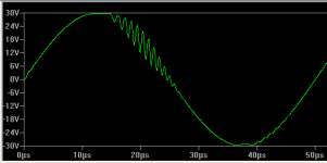
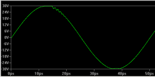
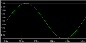
It is easy to see that both TPC and TMC do not recover from clipping as well as CMC. However, TPC is much worse than TMC, getting into an oscillation that does not cease until the polarity of the signal changes (interestingly, the negative polarity is more stable, probably due to differences in the output transistors.
BTW, the TPC and TMC versions have about the same amount of distortion reduction, and the total feedback around the output stage in each has about the same phase and gain margins. Also, small-signal squarewave response shows about the same amount of ringing.
Overall, TMC and TPC give up some stability in reducing distortion as compared to CMC, so they have to be evaluated carefully both in small signal and large signal. They are both very worthwhile techniques, but like any tool, must be properly applied. It appears that large-signal behavior of TPC is significantly worse than that of TMC when margins are close. Overall, I still am inclined to prefer TMC over TPC.
Cheers,
Bob
Cheers,
Bob
I've done some more simulations on CMC, TPC and TMC and have attached a zipped folder of three simulations (ready-to-run) of the three techniques showing how they behave when in modest clipping of a 20 kHz sinewave. All of these simulations are of the example amplifier I have used earlier, except that I lightened the HF load to 0.05uF and 2 ohms, doubled all of the base stopper resistors to 50 ohms and 5 ohms for the drivers and output transistors, respectively, and loaded the driver base stoppers with 100 pF to detract somewhat from the phase margin. Once again, the TPC and TMC designs were adjusted to give the same amount of THD-20 reduction as compared to CMC. THD-20 was on the order of 0.002%.
It is easy to see that both TPC and TMC do not recover from clipping as well as CMC. However, TPC is much worse than TMC, getting into an oscillation that does not cease until the polarity of the signal changes (interestingly, the negative polarity is more stable, probably due to differences in the output transistors.
BTW, the TPC and TMC versions have about the same amount of distortion reduction, and the total feedback around the output stage in each has about the same phase and gain margins. Also, small-signal squarewave response shows about the same amount of ringing.
Overall, TMC and TPC give up some stability in reducing distortion as compared to CMC, so they have to be evaluated carefully both in small signal and large signal. They are both very worthwhile techniques, but like any tool, must be properly applied. It appears that large-signal behavior of TPC is significantly worse than that of TMC when margins are close. Overall, I still am inclined to prefer TMC over TPC.
Cheers,
Bob
Cheers,
Bob
Attachments
Linear Technology - Design Simulation and Device Models (for free, of course!)
re math software - I'm used to the "undocumented" Maple symbolic features hidden in MathCad 11, v12 broke a lot of my worksheets and I never gave 13 a fair trial - the user forum heavyweights certainly seemed to always ask people to repost in version 11 for several years after the later versions
I am intrigued by the Sage math open source project http://www.sagemath.org/ but it looks like you just have to "explore" - I really like comprehensive documentation, working examples of what I'm trying to do - and especially a good indication of what the sw can't do or is so hard as to be impractical - so I don't waste my time
Last edited:
Hi Bob,
This might be very interesting, but I can't read *plt files. Where I can download a reader (for free, of course)?
Cheers,
E.
John Miles' 7470: HP-GL/2 Plotter Emulator should do.
jan didden
I stuck in 2 uH series output load isolation inductor and the clipping recovery ringing is pretty much gone with both TPC (well just 1 cycle), TMC (measured at the amp output)
I suppose Mr Curl will object that the 320 KHz low pass is "clearly audible", that would be -0.017 dB, 2nS group delay delta at 20 KHz re 1 KHz - them Golden Ears are pretty good!
it also hides the TPC "bump"
I suppose Mr Curl will object that the 320 KHz low pass is "clearly audible", that would be -0.017 dB, 2nS group delay delta at 20 KHz re 1 KHz - them Golden Ears are pretty good!
it also hides the TPC "bump"
Last edited:
Bob, one quick question for you (great book BTW)!
You wrote about quad emitter follower in NFB amps chapter. Did you just simulated the idea and what about oscillation problem when working in open loop. BTW I never seen a quad EF in real life amplifiers so I guess it`s hard to stabilize it.?
Thanks Borko.
You wrote about quad emitter follower in NFB amps chapter. Did you just simulated the idea and what about oscillation problem when working in open loop. BTW I never seen a quad EF in real life amplifiers so I guess it`s hard to stabilize it.?
Thanks Borko.
clipping
Thanks, jcx!
It seems that these *.plt files are not regular plot files, rather a kind of proprietary meta-files of LT. Here are the plots for those who don't have LT-spice.
From left to right: bridged TPC, bridged TMC and Miller compensation.
BTW, I also tried different values for the TPC compensation:
C=17p, C2=85p, R=2k2 respectively C=85p, C2=17p, R=2k2, but to no avail.
Cheers,
E.
Linear Technology - Design Simulation and Device Models (for free, of course!)
[snip]
Thanks, jcx!
It seems that these *.plt files are not regular plot files, rather a kind of proprietary meta-files of LT. Here are the plots for those who don't have LT-spice.
From left to right: bridged TPC, bridged TMC and Miller compensation.
BTW, I also tried different values for the TPC compensation:
C=17p, C2=85p, R=2k2 respectively C=85p, C2=17p, R=2k2, but to no avail.
Cheers,
E.
Attachments
Hi Bob,
This might be very interesting, but I can't read *plt files. Where I can download a reader (for free, of course)?
Cheers,
E.
Hi Edmond,
Sorry for the tardy response. Angela and I flew to Nashville yesterday to visit her daughter's family. That's where we plan to retire when the time comes.
The only way I ever read .plt files is to run the simulations. If you have LTspice on your computer, just run the simulation and the plot will come right up.
Cheers,
Bob
I stuck in 2 uH series output load isolation inductor and the clipping recovery ringing is pretty much gone with both TPC (well just 1 cycle), TMC (measured at the amp output)
I suppose Mr Curl will object that the 320 KHz low pass is "clearly audible", that would be -0.017 dB, 2nS group delay delta at 20 KHz re 1 KHz - them Golden Ears are pretty good!
it also hides the TPC "bump"
Hi jcx,
It makes sense that putting in the 2uH inductor improves dynamic performance of these compensation schemes. How much resistance did you have in parallel with the inductor?
Even John Curl agrees that 1 uH or less is OK. It would be interesting to see how well 1 uH and 2.2 ohms would do in this regard.
Cheers,
Bob
Bob, one quick question for you (great book BTW)!
You wrote about quad emitter follower in NFB amps chapter. Did you just simulated the idea and what about oscillation problem when working in open loop. BTW I never seen a quad EF in real life amplifiers so I guess it`s hard to stabilize it.?
Thanks Borko.
I've simulated the quad output stage (its not a quad EF as I recall, but rather has a diamond buffer as two of the stages). It simulates fine. But as with Triples and quads, the real-world application has to be done with care, including good power rail bypassing and HF isolation, good layout, and judicious use of base stopper resistors. I have not built an amplifier with it.
As I discuss in my book with reference to Triples, I also put base stoppers in the drivers. Also, I put HF LPF's in the power rail as the supply moves back from the main rail to the driver collectors and then the pre-driver collectors. These R-C LPFs drop very little voltage, but provide good loss at HF. For example, the first filter might use a 1-ohm resistor shunted to ground by 0.1uF and 100 uF. This combination also acts as a Zobel for the main rail, quieting any resonances there as well.
The Locanthi Triple is more than adequate for most designs, but the extra stage of a quad can in some cases improve things for use in no-feedback amplifiers. In some cases it can have better overall thermal stability than a Triple due to some Vbe cancellation in the diamond buffer if the devices are bolted together.
Cheers,
Bob
I'm not sure why the parallel R is necessary - Self points out that the 2uF || 8 Ohm "standard" is supposed to emulate ESL step-up Xfmr pri loading - which is completely wrong - they have series R, leakage L and usually are resonating with the load within a octave or 2 of 20 KHz
so why would a DIY builder add the parallel R just to look good on Stereophile's test bench with a load they can know they aren't using - and doesn't usefully emulate the ESL Xmfr anyway
I'm also unlikely to use ceramic piezo tweeters
is there another rationale for the R in parallel with the output L - wouldn't Pi Zobel networks provide enough damping for any dynamic loudspeaker/relatively sane Cable C load?
Last edited:
You wrote about quad emitter follower in NFB amps chapter. Did you just simulated the idea and what about oscillation problem when working in open loop. BTW I never seen a quad EF in real life amplifiers so I guess it`s hard to stabilize it.?
Thanks Borko.
It’s not often you see a quad diamond.
Have you ever seen a quad diamond before Bogdan?
As Bob says there are no problems with a “quad” diamond if you follow the “normal” guidelines that Bob mentions.
BTW the BIAS circuit that Bob are using with the quad is depending on the standing current in the VAS. Wouldn’t it be better to make the BIAS independent of the VAS current?
Cheers
Stein
No, I haven`t seen quad diamond in commercial amplifiers...you did?
I guess, first two stages are compensating each other and Vbe multiplier in the VAS stage is compensating driver and output transistors, that`s how I understood.
Also, I put HF LPF's in the power rail as the supply moves back from the main rail to the driver collectors and then the pre-driver collectors. These R-C LPFs drop very little voltage, but provide good loss at HF. For example, the first filter might use a 1-ohm resistor shunted to ground by 0.1uF and 100 uF. This combination also acts as a Zobel for the main rail, quieting any resonances there as well.
Cheers,
Bob
Bob if OPS is on separate PCB, is it better to separate LPF`s grounds from the zobel ground and connect each of them to the power supply`s main star ground through separate wires?
No, I haven`t seen quad diamond in commercial amplifiers...you did?
QUOTE]
No, never in a commercial design, I have only seen it on my own PC and on Andy's site (TT Buffer) before.
Stein
*.plt
Hi Bob,
No need to say sorry. We all have other things to do as well. So we should never expect an instant response.
The first time I ran your files, I got an error msg. (for some unknown reason). However, the second time it ran just fine (see post 1370). Thanks anyhow.
Cheers,
E.
Hi Edmond,
Sorry for the tardy response. Angela and I flew to Nashville yesterday to visit her daughter's family. That's where we plan to retire when the time comes.
Hi Bob,
No need to say sorry. We all have other things to do as well. So we should never expect an instant response.
The only way I ever read .plt files is to run the simulations. If you have LTspice on your computer, just run the simulation and the plot will come right up.
Cheers,
Bob
The first time I ran your files, I got an error msg. (for some unknown reason). However, the second time it ran just fine (see post 1370). Thanks anyhow.
Cheers,
E.
I'm not sure why the parallel R is necessary - Self points out that the 2uF || 8 Ohm "standard" is supposed to emulate ESL step-up Xfmr pri loading - which is completely wrong - they have series R, leakage L and usually are resonating with the load within a octave or 2 of 20 KHz
so why would a DIY builder add the parallel R just to look good on Stereophile's test bench with a load they can know they aren't using - and doesn't usefully emulate the ESL Xmfr anyway
I'm also unlikely to use ceramic piezo tweeters
is there another rationale for the R in parallel with the output L - wouldn't Pi Zobel networks provide enough damping for any dynamic loudspeaker/relatively sane Cable C load?
Hi jcx,
The R in parallel with the L damps resonances that may occur with different reactive loads. Note also, for those designs that place the Zobel on the downstream side of the coil, the presence of the parallel R is important to make sure that the loading of the Zobel network on the output emitter follower persists to high frequencies. This is important to the stability of the EF output stage.
Cheers,
Bob
- Home
- Amplifiers
- Solid State
- Bob Cordell's Power amplifier book