It would be correct if the VAS loading of the relevant compensation
networks was not existent or equivalent, but since it exist and is not
equivalent, and is easily measurable, this conclusion is wrong and
you are wrong as well.
I will mention that i used the same components values
for TPC and TMC sims, so that only aggravate your lack of clues
about what is discussed..
Unless trolling is the only thing you re interested in ?...
Who knows...
Never has so much bandwidth been expended on what is really just an electronic sleight of hand.
The fact that the loop gain enjoyed by the output stage is virtually identical with TMC and TPC indicates that the effect of so-called VAS loading is negligible when moving from one method to the other.
So-called TMC is a waste of time compared to TPC. This i have demonstrated in the links i posted and also by Syn08.
http://www.diyaudio.com/forums/soli...lls-power-amplifier-book-102.html#post2401622
Last edited:
So-called TMC is a waste of time compared to TPC.
Hi michael, I would respectfully disagree; as a nice to have feature, TMC provides Miller like phase linearity, which TPC doesn't and can't do. But how important is phase linearity in audio, in particular in a power amplifier, I don't know for sure. I though have absolutely no reason to believe it matters at all.
Anybody aware of any relevant commercial power amplifier that uses TPC?
Anybody aware of any relevant commercial power amplifier that uses TPC?
There was a British-made power amp some 15-ish years ago that claimed to use it. I think I read about it in HiFi News.
I'm afraid I cannot remember the company name, but it would appear that TPC has been used commercially.
Anyone else remember it?
The fact that the loop gain enjoyed by the output stage is virtually identical with TMC and TPC indicates that the effect of so-called VAS loading is negligible when moving from one method to the other.
This only prove that your VAS has poor gain, is already
heavy loaded well beyond TPC and TMC loading influence...
Indeed, the blameless style amp you re giving as exemple has
exactly those caracteristics, since the VAS must have about
60db gain, with another 60db or so provided by the current
mirrored LTP.
What about if the VAS has 100db gain, as in the sims i did post ?...
I don't have the article but Takahashi was a Sansui reseacher at the time:
"Design and Construction of High Slew Rate Amplifiers
This thesis concerns: 1) The design of an audio power amplifier that features a large amount of negative feedback over a wide range, yet has a high slew rate and low Transient Intermodulation Distortion (TIM). 2) The technical difficulties involved in the design of amplifiers based on a conventional single-pole compensation design, and advantages of a two-pole compensation design. 3) The proposed new circuit configuration for high slew rate. 4) The results of measurements of how much electric current flows in each compensation circuit of experimentally built power amplifiers, compared with the results of computation based on inverse Laplace transform. 5) Finally, the construction of an amplifier with a high slew rate of about 1,000V/usec.c
"
AES E-Library: Design and Construction of High Slew Rate Amplifiers
Hi wahab, I am still very uncomfortable with 130dB of loop gain and 40MHz of unity loop gain frequency, these values are out of any scale for an audio amp, at least according to the definition of "loop gain" I was taught. Could you please post a schematic with the relevant component values and the loop gain probe in place? Perhaps you are testing the Miller loop only? But even so, 40MHz unity loop gain frequency would be outlandish.
130db is the gain at DC, and as so, it s not exceptionnal..
Unity gain is at 30mhz,(not loop gain) , and that also common
for any non compensated amp.
Once the amp is compensated, unity gain decrease largely.
Here the full picture, with OLG uncompensated, OLG uncompensated
with VAS loaded by TPC/TMC networks, OLG compensated with TPC/TMC
and CLG of the amp...
Attachments
TPC vs TMC Simulation Results
I’ve run some amplifier simulations to try to arrive at apples-apples comparisons of straight Miller compensation, TPC and TMC. This should shed some light on the speculation about the performance of TPC vs. TMC in particular. The same fairly simple amplifier was simulated with the three different forms of compensation. My definition of apples-apples was that the gain crossover frequency of all three approaches was the same (1 MHz), that peaking of more than 1 dB was not allowed, and that all three arrangements had about the same amount of stability (good). Performance was evaluated with a 4-ohm load.
The amplifier simulated is a simple, medium-performance design similar to Figure 3.10 in my book. It uses a BJT input LTP with a tail current of 1mA, degenerated with 470 ohm resistors, and loaded with a two-transistor current mirror. The design uses a single-ended Darlington VAS loaded with a 10mA current source. The output stage is a Locanthi Triple with a single output pair of MJL21193/21194 transistors biased at 115 mA with RE=0.22 ohms.
Closed loop gain was set to 20 with a feedback network consisting of 3800 ohms and 200 ohms. Open-loop gain was inferred by setting closed loop gain to 50,000 by increasing the feedback resistor to 10 Meg with output DC offset trimmed to <10mV.
All versions had a gain crossover frequency of 1 MHz when driving a 4-ohm load. Closed loop gain and stability was checked with an additional shunt load of 1.0 ohm and 0.01 uF in series. This loading arrangement was also in place when compensation was designed. No output L-R network was used.
For purposes of discussion, the compensating capacitor that connects to the input of the VAS is designated as C1. The resistor forming the “T” with C1 and C2, if used, is designated as R1.
TPC was designed by making C1 and C2 equal in value and adjusting R1 downward in value until closed-loop gain peaking was 1 dB (300 kHz). The value of C1 and C2 was set to achieve a gain crossover frequency of 1 MHz. Square wave overshoot with TPC was 20%. The TPC design had 53 dB of loop gain at 20 kHz.
TMC was designed by making C2 five times C1. R1 was then adjusted downward until the closed-loop frequency response above the gain crossover frequency began to show signs of slightly diminished roll-off rate. C1 and C2 were set to achieve a gain crossover frequency of 1 MHz. The TMC and Miller designs had about 34 dB of loop gain at 20 kHz and exhibited no peaking or overshoot. Important performance comparisons are as follows:
THD-20:
Miller: 0.015 %
TPC: 0.007 %
TMC: 0.002 %
7th Harmonic:
Miller: 15 ppm
TPC: 11 ppm
TMC: 3 ppm
Slew Rate:
Miller: 50 V/us
TPC: 73 V/us
TMC: 52 V/us
In this apples-apples comparison TMC was superior to TPC in every regard except slew rate. As expected, slew rate for TPC was higher by about 40%. TMC provided a full 7:1 improvement in THD-20 over straight Miller compensation and a 5:1 improvement in 7th harmonic content.
TPC actually provided disappointing improvements over straight Miller compensation, and I make no claim that there are not more optimized versions of TPC that could have been used. Bear in mind my constraint of no more than 1 dB of peaking. It is possible that TPC wherein C1 and C2 are not equal may perform better while still obeying the 1 dB cap on peaking.
TPC provided only a 2:1 improvement in THD-20 over straight Miller compensation and only a 27% reduction in 7th harmonic content. How can this be, given that TPC has fully 19 dB more feedback at 20 kHz? The harmonics of interest don’t lie at 20 kHz; they lie at 60 kHz and above. By its very nature, TPC loop gain falls faster than 6 dB/octave in the ultrasonic range. At 60 kHz, TPC has only 8 dB more feedback than straight Miller compensation.
The attached Word document summarizes the results.
It is notable that TPC may do relatively better in 19+20kHz CCIF IM performance because in that test the IM products lie at frequencies where TPC provides more loop gain. I have not verified that with simulation, however.
Cheers,
Bob
Attachments
I’ve run some amplifier simulations to try to arrive at apples-apples comparisons of straight Miller compensation, TPC and TMC. This should shed some light on the speculation about the performance of TPC vs. TMC in particular. The same fairly simple amplifier was simulated with the three different forms of compensation. My definition of apples-apples was that the gain crossover frequency of all three approaches was the same (1 MHz), that peaking of more than 1 dB was not allowed, and that all three arrangements had about the same amount of stability (good). Performance was evaluated with a 4-ohm load.
The amplifier simulated is a simple, medium-performance design similar to Figure 3.10 in my book. It uses a BJT input LTP with a tail current of 1mA, degenerated with 470 ohm resistors, and loaded with a two-transistor current mirror. The design uses a single-ended Darlington VAS loaded with a 10mA current source. The output stage is a Locanthi Triple with a single output pair of MJL21193/21194 transistors biased at 115 mA with RE=0.22 ohms.
Closed loop gain was set to 20 with a feedback network consisting of 3800 ohms and 200 ohms. Open-loop gain was inferred by setting closed loop gain to 50,000 by increasing the feedback resistor to 10 Meg with output DC offset trimmed to <10mV.
All versions had a gain crossover frequency of 1 MHz when driving a 4-ohm load. Closed loop gain and stability was checked with an additional shunt load of 1.0 ohm and 0.01 uF in series. This loading arrangement was also in place when compensation was designed. No output L-R network was used.
For purposes of discussion, the compensating capacitor that connects to the input of the VAS is designated as C1. The resistor forming the “T” with C1 and C2, if used, is designated as R1.
TPC was designed by making C1 and C2 equal in value and adjusting R1 downward in value until closed-loop gain peaking was 1 dB (300 kHz). The value of C1 and C2 was set to achieve a gain crossover frequency of 1 MHz. Square wave overshoot with TPC was 20%. The TPC design had 53 dB of loop gain at 20 kHz.
TMC was designed by making C2 five times C1. R1 was then adjusted downward until the closed-loop frequency response above the gain crossover frequency began to show signs of slightly diminished roll-off rate. C1 and C2 were set to achieve a gain crossover frequency of 1 MHz. The TMC and Miller designs had about 34 dB of loop gain at 20 kHz and exhibited no peaking or overshoot. Important performance comparisons are as follows:
THD-20:
Miller: 0.015 %
TPC: 0.007 %
TMC: 0.002 %
7th Harmonic:
Miller: 15 ppm
TPC: 11 ppm
TMC: 3 ppm
Slew Rate:
Miller: 50 V/us
TPC: 73 V/us
TMC: 52 V/us
In this apples-apples comparison TMC was superior to TPC in every regard except slew rate. As expected, slew rate for TPC was higher by about 40%. TMC provided a full 7:1 improvement in THD-20 over straight Miller compensation and a 5:1 improvement in 7th harmonic content.
TPC actually provided disappointing improvements over straight Miller compensation, and I make no claim that there are not more optimized versions of TPC that could have been used. Bear in mind my constraint of no more than 1 dB of peaking. It is possible that TPC wherein C1 and C2 are not equal may perform better while still obeying the 1 dB cap on peaking.
TPC provided only a 2:1 improvement in THD-20 over straight Miller compensation and only a 27% reduction in 7th harmonic content. How can this be, given that TPC has fully 19 dB more feedback at 20 kHz? The harmonics of interest don’t lie at 20 kHz; they lie at 60 kHz and above. By its very nature, TPC loop gain falls faster than 6 dB/octave in the ultrasonic range. At 60 kHz, TPC has only 8 dB more feedback than straight Miller compensation.
The attached Word document summarizes the results.
It is notable that TPC may do relatively better in 19+20kHz CCIF IM performance because in that test the IM products lie at frequencies where TPC provides more loop gain. I have not verified that with simulation, however.
Cheers,
Bob
Hi Bob, great work, although I don't think it provides a fully apple to apple comparison between Miller, TPC and TMC. By enforcing "peaking of more than 1 dB was not allowed" you gave TPC a serious handicap to start with. TPC, as a second order system, will always exhibit a phase dip (equivalent to an overshoot in the time domain). By forcing this overshoot to be within 1dB you forced a suboptimal TPC configuration. If you would take minimum distortion and maximun phase margin as optimization criteria then you would for sure find out that TPC and TMC are almost exactly equivalent. I know, I tried it myself.
I have no idea why people are concerned about the TPC (or any other second order system) overshoot that it easily removed (if really required) by the input filter.
Otherwise, if the 1dB overshoot constraint is mantained, then I am sure TMC is and will always be the winner.
The mists clear... The Deltec DPA-50S, reviewed in HFN October 1988.There was a British-made power amp some 15-ish years ago that claimed to use it. I think I read about it in HiFi News.
According to the review, it used "double-pole/zero phase compensation" with three differential cascoded gain stages.
Last edited:
Hi Bob, great work, although I don't think it provides a fully apple to apple comparison between Miller, TPC and TMC. By enforcing "peaking of more than 1 dB was not allowed" you gave TPC a serious handicap to start with. TPC, as a second order system, will always exhibit a phase dip (equivalent to an overshoot in the time domain). By forcing this overshoot to be within 1dB you forced a suboptimal TPC configuration. If you would take minimum distortion and maximun phase margin as optimization criteria then you would for sure find out that TPC and TMC are almost exactly equivalent. I know, I tried it myself.
I have no idea why people are concerned about the TPC (or any other second order system) overshoot that it easily removed (if really required) by the input filter.
Otherwise, if the 1dB overshoot constraint is mantained, then I am sure TMC is and will always be the winner.
Hi YWN,
From reading your post I'm wondering if there is some confusion between frequency response peaking and square wave overshoot. I put an explicit limit of 1 dB of frequency response peaking on the TPC arrangement, but I did not put a restriction on time-domain overshoot. Anyway, the overshoot was not limited to 1 dB.
So, in my mind, the real question is how much frequency response peaking should be allowed in a reasonable comparison. I agree completely that my choice of 1 dB influences the result of the comparison. Do you believe that a 3 dB peak in ultrasonic response is appropriate to allow in a high quality amplifier? It seems to me that a second-order feedback system with a 3 dB peak is a bit in the zone of conditional stability.
Anyway, you are bringing up a very good point about what we consider apples-apples.
BTW, take a look at the table I provided in the Word document and note the very large in-band peak in feedback factor at 7.5 kHz. I can't believe that such a disturbance in-band is good for sonics. I describe this phenomenon of TPC in my book and show that it can be mitigated by a small bridging capacitor across the T (Bridged T Compensation).
Cheers,
Bob
TPC commercial products
The OPTI-MOS range of amps still offered by ZuS (Canada) and referred to earlier By Bob are claimed to use TPC. Seeing that the OPTI-MOS white paper on their website is credited to Randy Slone, the designer, that's likely to be the case.Anybody aware of any relevant commercial power amplifier that uses TPC?
The simulator "lies" - occasionally..
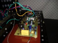
Thanks for the wonderful in - depth discussion on TPC/TMC. I have been in the "trenches" , actually building/ testing/abusing different topologies w/TMC on my "testbed" (pix1).
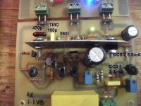
Similar to my main (and best attempt - AX - pix 2). 35db at 20K (simulated) , 875k GCF ,and "the bump" just above UG ? I got that with 470R or lower Rtmc (simulated). I ran the real amp with 560R (like E. stuarts example). I also ran a 10k SW into it with a resistive load ... perfect , no overshoot .. textbook.
I then listened to it , sounded wonderful at moderate volumes and outright glorious at major levels (150w w/ 400w transients). I put a switch on Rtmc and was able to A/B instantly (almost - shut down , "switch" - power up).
TMC's effect was both noticable and beneficial , not even on a subjective level (quite easy to notice). Best amp I have ever heard - really. (simple , too)
Tried it on a very similar topology with a bootstrapped current source. This attempt gave me an oscillator. I increased my TMC ratio 6:1 -100p/560p- upped Rtmc to 1K , all was well)Even then , TMC did not have as a pronounced effect with the bootstrapped current source. The feedback of the bootstrap interfered with TMC .. the simulator did not predict this errata , but showed this topology as the clear "winner". 
The winner (audibly) was the "blameless" /w TMC (AX-pix 3) , I compared it to 2 other popular amps (original symasym and a luxman clone) and the margin was noticeable. These real world tests were done on a standard EF2 - mje15034/35 / njw0281/0302 OPS. TMC is nice , but should be applied "carefully" , not all amps/topologies will benefit from it.
Thanks for the wonderful in - depth discussion on TPC/TMC. I have been in the "trenches" , actually building/ testing/abusing different topologies w/TMC on my "testbed" (pix1).
TMC was designed by making C2 five times C1. R1 was then adjusted downward until the closed-loop frequency response above the gain crossover frequency began to show signs of slightly diminished roll-off rate. C1 and C2 were set to achieve a gain crossover frequency of 1 MHz. The TMC and Miller designs had about 34 dB of loop gain at 20 kHz and exhibited no peaking or overshoot. Important performance comparisons are as follows:
Similar to my main (and best attempt - AX - pix 2). 35db at 20K (simulated) , 875k GCF ,and "the bump"
just above UG ? I got that with 470R or lower Rtmc (simulated). I ran the real amp with 560R (like E. stuarts example). I also ran a 10k SW into it with a resistive load ... perfect , no overshoot .. textbook.I then listened to it , sounded wonderful at moderate volumes and outright glorious at major levels (150w w/ 400w transients). I put a switch on Rtmc and was able to A/B instantly (almost - shut down , "switch" - power up).
TMC's effect was both noticable and beneficial , not even on a subjective level (quite easy to notice). Best amp I have ever heard - really. (simple , too)
Tried it on a very similar topology with a bootstrapped current source. This attempt gave me an oscillator.
I increased my TMC ratio 6:1 -100p/560p- upped Rtmc to 1K , all was well)Even then , TMC did not have as a pronounced effect with the bootstrapped current source. The feedback of the bootstrap interfered with TMC .. the simulator did not predict this errata , but showed this topology as the clear "winner". The winner (audibly) was the "blameless" /w TMC (AX-pix 3) , I compared it to 2 other popular amps (original symasym and a luxman clone) and the margin was noticeable. These real world tests were done on a standard EF2 - mje15034/35 / njw0281/0302 OPS. TMC is nice , but should be applied "carefully" , not all amps/topologies will benefit from it.
Attachments
Tried it on a very similar topology with a bootstrapped current source. This attempt gave me an oscillator.
The winner (audibly) was the "blameless" /w TMC (AX-pix 3) , I compared it to 2 other popular amps (original symasym and a luxman clone) and the margin was noticeable. These real world tests were done on a standard EF2 - mje15034/35 / njw0281/0302 OPS. TMC is nice , but should be applied "carefully" , not all amps/topologies will benefit from it.
Hi ostripper,
As I have mentioned, I have been trying TMC on the BAKSA (with bootstrapped VAS) so I am curious how to look out for oscillations. I haven't heard any degradation in sound quality and I have been monitoring the temperature of all transistors and all seem to be normal temperature (about 10 degrees above ambient).
I suppose I need to get my signal generator and CRO out.
I should mention, as I have an off board output inductor I have been connecting TMC before the zobel or inductor.
86pF/330pF/470R
EDIT: I just realised I should have posted in your thread rather than here, sorry.
regards
Last edited:
Hi ostripper,
As I have mentioned, I have been trying TMC on the BAKSA (with bootstrapped VAS) so I am curious how to look out for oscillations. I haven't heard any degradation in sound quality and I have been monitoring the temperature of all transistors and all seem to be normal temperature (about 10 degrees above ambient).
I suppose I need to get my signal generator and CRO out.
I should mention, as I have an off board output inductor I have been connecting TMC before the zobel or inductor.
86pF/330pF/470R
EDIT: I just realised I should have posted in your thread rather than here, sorry.
regards
Either thread , it's not OT
I learn here , apply over "there" .Sig. gen. +CRO = absolutely essential to find the truth.
"look for oscillations" ...maybe a smokin' zoble resistor (sniff, sniff)...
OS
Hi YWN,
From reading your post I'm wondering if there is some confusion between frequency response peaking and square wave overshoot. I put an explicit limit of 1 dB of frequency response peaking on the TPC arrangement, but I did not put a restriction on time-domain overshoot. Anyway, the overshoot was not limited to 1 dB.
Bob
Hi Bob, you are right, it was late here and I was half asleep. I thought you were talking about an overshoot in the time domain rather than in the frequency domain, as it is clear this morning.
Anyway, I would still barely consider the TPC implementation in your analysis as optimal; as you noticed yourself, the TPC improvement over Miller is "dissapointing". I still hold on to the challenge I described in another message, above: give me an optimally compensated TMC amp and I'll deliver back a TPC compensated version, with about the same unity loop gain frequency, phase margin and THD @ 20KHz. The rest is a trade between the higher TPC slew rate and the better TMC phase linearity. If you want me to do this on your example, let me know.
Otherwise, as tempting as it might be, I think we should keep "sonics" out of this disccussion. Unfortunately, there is no metric for "sonics" other than subjective testimonials.
Last edited:
The mists clear... The Deltec DPA-50S
Shame they went hush-hush on compensation technique : http://www.deltecprecisionaudio.com/images/stories/products/DPA-MA1/ma1_product_brief.pdf
Last edited:
130db is the gain at DC, and as so, it s not exceptionnal..
Unity gain is at 30mhz,(not loop gain) , and that also common
for any non compensated amp.
Once the amp is compensated, unity gain decrease largely.
Here the full picture, with OLG uncompensated, OLG uncompensated
with VAS loaded by TPC/TMC networks, OLG compensated with TPC/TMC
and CLG of the amp...
Am sorry wahab, but without schematics and some details on the analysis methodology I myself cannot really follow your results and comments.
I must be dense, but in all truth, "Unity gain is at 30mhz,(not loop gain) , and that also common for any non compensated amp. Once the amp is compensated, unity gain decrease largely" doesn't make any sense to me.
I'll leave the discussion about your results to those who can.
Deltec 2-pole compensation
Some more info here:
the Deltec / DPA webpages
Shame they went hush-hush on compensation technique : http://www.deltecprecisionaudio.com/images/stories/products/DPA-MA1/ma1_product_brief.pdf
Some more info here:
the Deltec / DPA webpages
- Home
- Amplifiers
- Solid State
- Bob Cordell's Power amplifier book