Before I forget ---- Regarding SR margin ---
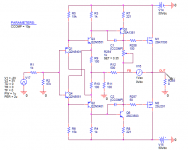
As we get closer to the amps SR, the waveform begins to distort... bending more into triangle shape. We know it takes very little waveform change to a sine wave to produce harmonics at -100dBv.
View attachment 582849
To keep the HF harmonic distortion as low as possible, then just barely approaching SR of amp would start increasing distortion. As there is often out of band HF at significant level going into PA, I would consider >20KHz (50KHz-100KHz?) in SR calc.
And as loudspeaker loads vary in Z, a better SR calc number might replace the V in SR formula (2 pi f Vp) with (2*P*Z)^1/2. A healthy SR margin will assure lowest distortion for all conditions.
THx- RNMarsh
This is largely true, and I and others have always advocated this. When an amplifier goes into slew rate limiting, as depicted in your drawing, this is analogous to hard clipping of an amplifier in the rate-of-change domain. Like amplifier amplitude-related distortion, smaller degrees of distortion increase begin to appear long before clipping or slew limiting. This is especially the case for individual stages where their distortion behavior is considered in the open loop. Also, think of "soft" clipping and "soft" slew rate limiting. So in a conventional arrangement, margin against slew rate limiting definitely plays a role in reducing distortion.
This is an eminently measurable phenomena. This is one reason why 20 kHz THD at high amplitude is a good measurement for characterizing this. Obviously THD at even higher frequencies is desirable as well, but not as easy to accurately measure with many analyzers (they need more residual bandwidth in order not to cut into the amplitude of the harmonics).
19+20kHz CCIF is also a good measurement for characterizing HF performance, as it causes the distortion products to land at LOWER frequencies that can be measured with a spectrum analyzer. The challenge here is that spectrum analyzers that have 120 dB dynamic range are not readily available at reasonable prices. Also, 19+20kHz CCIF tends to produce smaller levels of spectral components than THD-20 for a given amplifier and peak operating level. Many of the newer APs do a pretty good job in this area, and one should look at John Atkinson's amplifier review measurements, which very fortunately usually include 19+20 kHz CCIF.
The caveat to slew rate margin reducing HF distortion is slew on demand circuits that result from current on demand circuit topologies. Slew on demand almost always depends on the circuitry somewhere going into a somewhat different operating mode, sort of like leaving class A and going into class B operation in the IPS or VAS.
So if you are claiming that slew rate margin that is achieved through current on demand will enhance HF distortion behavior, you will probably be disappointed. The slew rate margin that is achieved without or before current on demand behavior is what really counts in this regard.
In my view, a power amplifier should usually have at least 50 v/us slew rate achieved without current on demand, and this is not difficult to achieve in either VFA or CFA power amplifiers.
Cheers,
Bob
The caveat to slew rate margin reducing HF distortion is slew on demand circuits that result from current on demand circuit topologies. Slew on demand almost always depends on the circuitry somewhere going into a somewhat different operating mode, sort of like leaving class A and going into class B operation in the IPS or VAS.
Mr. Cordell, I believe what you are saying is, in general, incorrect. It applies only in the cases where the current is limited by a bias current. Once the bias current limit is reached, the amplifier enters in a non linear region as you say, the loop gain drops and there's nothing to linearize the amplifier. This is essentially a large signal behavior.
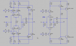
Do the following gedanken experiment. Imagine you are looking at (a) the output of a long tail pair, Miller compensated VFA amplifier, and (b) the output of a standard CFA with diamond buffer at the input, also Miller compensated. The input signal is a square wave with zero rise and fall times, of variable amplitude.
Set the pulse generator to a very low level, say 1mV. Up to a phase shift, what you will see at the output is a signal with exponential rise and fall times, the rise time being determined by the amplifier bandwidth Tr[nS]=0.35/BW[MHz] This rise time is the same if you double the input level to 2mV, so that the apparent slew rate will double. This happens if you further increase the input amplitude, until you will reach the slewing limit. From this point further, the slew rate will be constant with increasing the input level and is given by the rate of charging the Miller cap by twice the input stage bias current, SR=2*Ibias/Cmiller. At this point, indeed the input stage is in some sort of class B non linearity, since all the bias current is flowing through Cmiller.
Now look at (b). As the current charging the Miller cap is essentially Vout/Rfeedback, there is virtually no limit. Whatever amplitude the input signal has, if Rf is small enough, the Miller cap will charge at a higher rate, proportional to the input signal. Therefore, the property mentioned above (of the apparent slew rate increasing with the input signal) is conserved up to the maximum output voltage swing. And no stage in the amplifier is, in this case, under any circumstances, entering in nonlinearities.
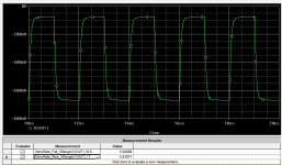
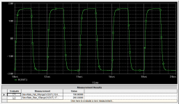
I'm attaching a classic CFA schematic with a closed loop gain of 6 (sorry, no time to fit a bias scheme for vertical mosfets) and the results for a 100mVpp input and the 6Vpp input, both 500KHz. As you see, the rise time is approximately constant and the apparent slew rate is proportional to the input signal amplitude. Theoretically, if there's nothing else to charge but the Miller cap, this proportionality will hold until the amplifier output reaches the maximum swing (otherwise said, until the amplifier clips).
In the real world though, there's more than the Miller cap, so from a certain input level the CFA will indeed enter in slewing limitation, some active devices will enter in nonlinearities, and the proportionality is lost. This can be avoided to a certain degree by a more advanced CFA topology and careful design, hence the CFA op amps with thousands of V/uS at full output.
The bottom line is that an ideal Miller compensated CFA will never get into slewing limitations/distortions. This is in contrast to an ideal Miller compensated long tail pair basic VFA, which will, sooner or later, enter into slewing limitations. Of course, there are ways to avoid slewing limitations in a VFA, also possible to implement current on demand in a VFA.
Attachments
Last edited:
waly, bob...... current on demand isnt necessarily only way - I was relating this to practical IC opamp packaging as a possible reason for its popular use in those products. discrete isnt bound by such packaging power dissipation limitations.
Lets do something new...... someone do a monti-carlo on SR (Cc ?) vs THD vs freq. Pick topology of choice or several. See data as one isnt just into SR limiting (clipping-like) but approaching full SR limit.
THx-RNMarsh
Lets do something new...... someone do a monti-carlo on SR (Cc ?) vs THD vs freq. Pick topology of choice or several. See data as one isnt just into SR limiting (clipping-like) but approaching full SR limit.
THx-RNMarsh
Lets do something new...... someone do a monti-carlo on SR (Cc ?) vs THD vs freq. Pick topology of choice or several. See data as one isnt just into SR limiting (clipping-like) but approaching full SR limit.
Sure, where do I send the invoice?
LTSpice is available for free, what about doing it yourself and let everybody know the amazing findings?
Sure, where do I send the invoice?
LTSpice is available for free, what about doing it yourself and let everybody know the amazing findings?
You constant wining about everything RNMarsh has to say got old a long time ago. Just thought I'd pint that out. You obviously missed it.
You obviously missed it.
Yes, I missed it, sorry.
I understand you are volunteering to do the Monte Carlo simulations envisioned by Mr. Marsh. Can't wait to see your results and learn something new.
Hi Waly,
It isn't necessary to badger anyone to get your point across. It is in fact, getting very old. It also distracts from the main points being discussed, and I for one would like to see what pops out of it.
If you have contrary proof for something you want to argue, then post it. If not, keep your objections to a normal polite discussion among professionals.
-Chris
It isn't necessary to badger anyone to get your point across.
Ok, ok.
Attachments

Sure, where do I send the invoice?
LTSpice is available for free, what about doing it yourself and let everybody know the amazing findings?
anyone can do it... wasnt addressed to only you. who ever is curious to see results of distortion as it approaches SR limiting can do the work.
Should be interesting re conditions et al.
THx-RNMarsh
Bob,Yes, this is an extremely handy rule of thumb for silicon bipolar transistors and silicon diodes. Note it also comes out to about 18mV for doubling of current. This slope factor is related to kT/q and changes with temperature.
Also, interestingly, MOSFETs and JFETs have a subthreshold conduction region below gate voltages where the square law would predict zero current and zero transconductance. Plot drain current and transconductance with the ordinary LTspice model and you will see them go to zero in a way that indicates a discontinuous derivative. Mother Nature does not usually like discontinuities. This discontinuity and subthreshold conduction for MOSFETs has previously been discussed here, with references to the fix by using the EKV model or the newly introduced Ksuthres parameter in the VDMOS LTspice model (thank you, Mike Engelhardt!).
As the current approaches the subthreshold region, the FET behavior transitions from a square law to an exponential law, the latter being like that of a BJT. However, the slope, instead of being about 60mV/decade, is often in the range of 150-300 mV/decade or more. This translates to lower gm at a given current in the subthreshold region than that of a BJT.
Cheers,
Bob
Thank you for all of the information, and for taking the time to reply. I did some light reading about Ludwig Boltzmann and his constant. I now understand your answer better
") .
. I am really enjoying your book so far. I know that I am not at the same level of understanding as some members, and will not take 100% out of your book the first time I read it...But I guess thats why this forum is here
. One day I might even be a contributing member! 
Cheers,
Tim
Waly , i see a post in number 7410 ..
what is the name of the animal ? ..
is that yours ?
It's me, the badger.
It's me, the badger.
I new it. Not really human.
Headlines: First badger to earn EE degree.
Mr. Cordell, I believe what you are saying is, in general, incorrect. It applies only in the cases where the current is limited by a bias current. Once the bias current limit is reached, the amplifier enters in a non linear region as you say, the loop gain drops and there's nothing to linearize the amplifier. This is essentially a large signal behavior.
Do the following gedanken experiment. Imagine you are looking at (a) the output of a long tail pair, Miller compensated VFA amplifier, and (b) the output of a standard CFA with diamond buffer at the input, also Miller compensated. The input signal is a square wave with zero rise and fall times, of variable amplitude.
Set the pulse generator to a very low level, say 1mV. Up to a phase shift, what you will see at the output is a signal with exponential rise and fall times, the rise time being determined by the amplifier bandwidth Tr[nS]=0.35/BW[MHz] This rise time is the same if you double the input level to 2mV, so that the apparent slew rate will double. This happens if you further increase the input amplitude, until you will reach the slewing limit. From this point further, the slew rate will be constant with increasing the input level and is given by the rate of charging the Miller cap by twice the input stage bias current, SR=2*Ibias/Cmiller. At this point, indeed the input stage is in some sort of class B non linearity, since all the bias current is flowing through Cmiller.
Now look at (b). As the current charging the Miller cap is essentially Vout/Rfeedback, there is virtually no limit. Whatever amplitude the input signal has, if Rf is small enough, the Miller cap will charge at a higher rate, proportional to the input signal. Therefore, the property mentioned above (of the apparent slew rate increasing with the input signal) is conserved up to the maximum output voltage swing. And no stage in the amplifier is, in this case, under any circumstances, entering in nonlinearities.
I'm attaching a classic CFA schematic with a closed loop gain of 6 (sorry, no time to fit a bias scheme for vertical mosfets) and the results for a 100mVpp input and the 6Vpp input, both 500KHz. As you see, the rise time is approximately constant and the apparent slew rate is proportional to the input signal amplitude. Theoretically, if there's nothing else to charge but the Miller cap, this proportionality will hold until the amplifier output reaches the maximum swing (otherwise said, until the amplifier clips).
In the real world though, there's more than the Miller cap, so from a certain input level the CFA will indeed enter in slewing limitation, some active devices will enter in nonlinearities, and the proportionality is lost. This can be avoided to a certain degree by a more advanced CFA topology and careful design, hence the CFA op amps with thousands of V/uS at full output.
The bottom line is that an ideal Miller compensated CFA will never get into slewing limitations/distortions. This is in contrast to an ideal Miller compensated long tail pair basic VFA, which will, sooner or later, enter into slewing limitations. Of course, there are ways to avoid slewing limitations in a VFA, also possible to implement current on demand in a VFA.
Dude
Good post you are exaxtly right and I totaly agree.
"Of course, there are ways to avoid slewing limitations in a VFA, also possible to implement current on demand in a VFA."
That is what I prefer doing.
Cheers
S
Attachments
Member
Joined 2009
Paid Member
Current On Demand, or COD. That's a fish isn't it.
I don't get what is the difference between COD and low impedance. I always thought low impedance was the normal descriptor for being able to pull current out of something

I don't get what is the difference between COD and low impedance. I always thought low impedance was the normal descriptor for being able to pull current out of something
It is extremely unlikely that the reason is sound quality because there are so many different topologies and methods (class (A) B, class D, SET, Hybrid, et al) which all have their fanatical defenders as giving 'the best' sound quality.
So, invoking Occam's Razor would point to anything but sound quality.
Jan
I don't get what is the difference between COD and low impedance. I always thought low impedance was the normal descriptor for being able to pull current out of something
Which is wrong.
Cheers
S
Member
Joined 2009
Paid Member
Which is wrong.
Cheers
S
Current flows when there is a potential difference and it flows in proportion to the impedance. Low impedance = lotsa current. Which bit of that is wrong, or is COD one of those nonsense labels that means only what somebody wanted it to in order to achieve some personal goal ??????
- Home
- Amplifiers
- Solid State
- Bob Cordell's Power amplifier book