See, we are talking about high level properties of the CFA before defining the concepts we are operating with.
In my book, "current on demand" is the property of a circuit topology to provide to the parasitic and/or compensation capacitor(s) enough current to avoid the current starving slewing limitation. A topology with current on demand has, by definition, no fundamental slew rate limit. Not much to do with the class A(B) output current. See for example
http://www.analog.com/media/en/training-seminars/tutorials/MT-034.pdf
http://www.analog.com/media/en/training-seminars/tutorials/MT-057.pdf
https://books.google.ca/books?id=dz...Current on demand" "current feedback"&f=false
It happens that the classic CFA topology (diamond buffer style) inherently implements "current on demand", but other topologies (some in pure VFAs) can implement this feature as well.
I tend to agree with your usage.
While a class AB output stage functionally provides current on demand, this is not what we are referring to when the term "current on demand" is being used, at least in the context of audio power amplifiers.
In the current context, it usually refers to the IPS or VAS going out of class A operation into effectively a class B mode, usually in a push-pull sense. This means that the stage can usually deliver more than twice its idle current.
Current on demand (COD) operation is not limited to a CFA.
If one has COD in the input stage of a Miller-compensated VFA, for example,
more than twice the tail current of an LTP input stage is available to charge the Miller compensating capacitor, hence greater slew rate.
One interesting example of a VFA IPS with some COD behavior is the full-complementary JFET input stage with floating tail popularized by John Curl. It uses two opposite-sex LTPs with their tails connected together by a bias-setting resistor and takes advantage of the depletion-mode nature of JFETs that creates a voltage across this resistor.
If over-driven out of its class A region, one NJFET and one PJFET will be on and cause a greater voltage drop across the bias resistor to make additional current available. The other two JFETs will be off. This is just one example of a VFA COD IPS that comes to mind.
Note that in some instances when a COD IPS goes into COD mode, the net transconductance of the stage may change. If so, this can lead to distortion and different incremental ULGF values.
COD operation is also applicable to the VAS. A single-ended VAS loaded with a current source is COD in only one polarity of slew. Many push-pull VAS have a COD characteristic. This comes into play in increasing the slew rate if the available VAS current to charge output stage load capacitance and/or VAS output node compensating capacitance is insufficient. Note that the slew-limiting stage in a power amplifier can either be the IPS or VAS.
It is my preference that neither the IPS nor the VAS should ever have to go out of class A in a high-end amplifier. Achieving high slew rate through COD is almost like cheating, in my personal opinion, because it will generally not reduce distortion (I know there are those who will disagree). Of course, the marketing folks may love it. It is not that difficult to achieve far more slew rate than needed while keeping the IPS and VAS in class A and not needing to go to an unreasonably high ULGF.
Cheers,
Bob
..............
It is not that difficult to achieve far more slew rate than needed while keeping the IPS and VAS in class A and not needing to go to an unreasonably high ULGF.
Cheers,
Bob
I would like to know what is unreasonably high ULGF? I showed practical amp with the ULGF of more then 5 MHz and don't think it's unreasonably high. I think that it could be even higher with mosfet OPS. Main problem could be the drivers, I don't see to much choice there.
The need for higher ULGF is not to get higher SR, but to have higher Loop Gain at 20 kHz or more.
Best wishes
Damir
Hi Damir,
Unreasonably high ULGF is the case where a designer with a given set of skills and eperience sets ULGF too high for comfort and reliability for the technology used, and/or when the phase margins and gain margins are inadequate under any reasonable loading conditions. Another example of stretching it too far would be the use of too-small gate stopper resistors in a MOSFET output stage to make it faster and allow higher ULGF, all at the risk of the possibility of MOSFET parasitic oscillations.
I tend to be conservative, usually opting for ULGF of 2MHz or less, even with vertical MOSFETs, but that is a designer's personal choice.
In a conventional Miller compensated amplifier, achievable slew rate is approximately in direct proportion to ULGF. Higher ULGF increases slew rate and decreases THD-20, all else remaining approximately equal.
Cheers,
Bob
Well funny thing is, I had been using for many years a VFA amp of same power output and very low THD etc for several years. On ESL and Dynamic speakers. I really didnt know that those other mainstream mfr made any CFA amps until I searched. After hearing the CFA from DADoD, I bought a new Marantz CFA (7025) expecting it to be better than the VFA. But I was disappointed in the sound, overall. It was better in imaging details (a good thing). But bass was not as accurate and deep etal. I had 4 each 15 inch Cerwin-Vega high effec bass drivers which are amazing.... but not with the Marantz. Not enough current capability for low Z of paralleled bass drivers. So I went back to the VFA PA. So, not wanting to make a DIY version of DADoD amp, I sent it to my friends in Bangkok to make for me. Meanwhile, I upgraded the speakers to JBL M2's.
I think you will have a hard time convincing me the amps heard are all the same sounding. No collusions IMO. Some time soon I will have a pair of DADod CFA to power the M2. I hope i can consider my quest finished... just in time to have a few remaining years to listen and enjoy the sound of music.
I have only found characteristic differences in the test data profiles, which i have told. The differences which stand out are --- some more SR margin, and a flat thd vs freq vs power vs load... all at very, very low distortion. I have mfr working up a full set of specs.
THx-RNMarsh
I'm still in SE Asia... Cambodia, Thailand, Nepal. No good sound for 3 months. :-(
Thanks for the information. So would you confirm that Dadod's amp has no issues handling low frequency sounds and is more or less a full spectrum amplifier? And has great sound quality in the mid and high frequency too...
Thanks for the information. So would you confirm that Dadod's amp has no issues handling low frequency sounds and is more or less a full spectrum amplifier? And has great sound quality in the mid and high frequency too...
yes, I can confirm that for you. I can tell more when i have them connected to the M2's.
THx-Richard
Richard I wish you many, many years of good health and musical enjoyment!
And I am not going to argue with people's personal preferences, however obtained; as I mentioned before, people swear by the most different and completely opposite conceptual amps as you can think of, as being The best Sounding. So that is unfortunately no help to decide which topology is objectively better in terms of accuracy, the original HiFi concept.
So it seems that at this point we just lack the tools to decide that which is coincidental is or is not causal.
So the quest continues....
Jan
Thank you, Jan.
For me "like" means closest in sound to the original or master source. I started making my own recordings and attending others recordings to know what the recorded master ought to sound like for reference listening. Those systems which sound closer to real musical instruments are my reference.
This is different from liking certain kinds of distortions. I also rely on tests... the best which do well on both win favor with me. Would my system now fool me into thinking real musical instruments are playing in my room. No. But within the limitations of 2 channels, it is very accurate to the source.
THx-Richard
Last edited:
Nicely put and that's exactly why we love CFA in power amps. It's not alone CFA approach to ensure good sounding amps, many other spices involved too, anyway without it our life would be much more boring. Nothing new said, all present know basics way better than me, nonetheless we're all allowed to cook and play. Learn to ride the beast, enjoy. 😎Now if you look into a classic CFA topology, you'll note that the Miller (or any other parasitic cap) charging current is limited only by the feedback resistor and the output voltage swing. Since the available current depends on the output swing the more harder you drive the amp, the more charging current you get (therefore "current on demand"), hence the non slewing characteristic of the classic CFA topology. In a long tail pair VFA, the Miller cap affects both the slew rate and the amplifier bandwidth, while in a CFA classic topology it affects mostly the amplifier bandwidth (and not the slew rate).
L.T. as manufaturer have provided simplified internal schematic for both IC .
Yes we also have made the "H-bridge" input stage for DSL drivers. Remember if you narrow the application enough, that is if you fully specify the closed-loop gain, the load drive, and BW limit the input, you can make either work almost indistinguishably from each other.
Been following this thread closer for the past week have to admit it has been a bit perplexing with this at least for me rather "new", and as davada put it, buzz word "Current On Demand" (COD), maybe I never payed much attention to it as I just can't recall this buzz word.
Or should we interpret it as:
"current on demand" is a marketing gimmick invented on XYZemiconductors Inc.s' "Ministry of Truth" propaganda department?
Anyway, so I went searching the internet, and where my search engine of choice threw up 3 Analog sources, MT-034, MT-056 and MT-056, but not much more.
Putting current on demand within "" forces search engine to come up with the exact phrase and another one came up mentioning "current on demand":
High Fidelity Headphone Amplifier (Rev. B) - Texas Instruments
http://www.ti.com/lit/ds/symlink/tpa6120a2.pdf
where it says:
"Three key features make current-feedback amplifiers
outstanding for audio. The first feature is the high
slew rate that prevents odd order distortion
anomalies. The second feature is current-on-demand
at the output that enables the amplifier to respond
quickly and linearly when necessary without risk of
output distortion. ..." etc.
Regarding force-charging/discharging the miller cap intermittently "faster" on demand, as mentioned in Analogs' papers, doesn't this, what appears to me as an nonlinear behavior, at some point equate more distortion?
The VFA with a classic LTP is, in opposition to CFA COD, limited to a specific CCS current supply, ok then, let's crank up the CCS and we have suddenly a lil' bit "faster" amp while at the same time the LTP stage may be a bit more sub-optimal seen from a its linear working condition stand point.
CFAs' then, they may work optimally at normal working conditions producing low distortion, but as soon as distortion on the output occurs for what ever reasons (not to forget things such as misbehaving difficult loudspeakers or RF interferences picked up by the antenna, excuse me, I meant those long speaker cables..), doesn't a CFA start to distort more when it has to drift into COD-mode and leaving the low-distortion-optimal working condition?
CFAs' may be faster and more stable than VFA, but I can't find much dissertation on whether the distortion is kept low also under conditions where it drifts into COD mode, and perhaps it doesn't matter too much for most of us lacking bat ears requiring UHF amps.
Analog also mention in one of their op-amp material that also VFAs' can be made COD.
BTW, could anyone explain on the CFA property claims by TI, quote: "high slew rate that prevents odd order distortion anomalies"?
ps: In my book, everyone is entitled a book.")
TOP
Or should we interpret it as:
"current on demand" is a marketing gimmick invented on XYZemiconductors Inc.s' "Ministry of Truth" propaganda department?
Anyway, so I went searching the internet, and where my search engine of choice threw up 3 Analog sources, MT-034, MT-056 and MT-056, but not much more.
Putting current on demand within "" forces search engine to come up with the exact phrase and another one came up mentioning "current on demand":
High Fidelity Headphone Amplifier (Rev. B) - Texas Instruments
http://www.ti.com/lit/ds/symlink/tpa6120a2.pdf
where it says:
"Three key features make current-feedback amplifiers
outstanding for audio. The first feature is the high
slew rate that prevents odd order distortion
anomalies. The second feature is current-on-demand
at the output that enables the amplifier to respond
quickly and linearly when necessary without risk of
output distortion. ..." etc.
Regarding force-charging/discharging the miller cap intermittently "faster" on demand, as mentioned in Analogs' papers, doesn't this, what appears to me as an nonlinear behavior, at some point equate more distortion?
The VFA with a classic LTP is, in opposition to CFA COD, limited to a specific CCS current supply, ok then, let's crank up the CCS and we have suddenly a lil' bit "faster" amp while at the same time the LTP stage may be a bit more sub-optimal seen from a its linear working condition stand point.
CFAs' then, they may work optimally at normal working conditions producing low distortion, but as soon as distortion on the output occurs for what ever reasons (not to forget things such as misbehaving difficult loudspeakers or RF interferences picked up by the antenna, excuse me, I meant those long speaker cables..), doesn't a CFA start to distort more when it has to drift into COD-mode and leaving the low-distortion-optimal working condition?
CFAs' may be faster and more stable than VFA, but I can't find much dissertation on whether the distortion is kept low also under conditions where it drifts into COD mode, and perhaps it doesn't matter too much for most of us lacking bat ears requiring UHF amps.
Analog also mention in one of their op-amp material that also VFAs' can be made COD.
BTW, could anyone explain on the CFA property claims by TI, quote: "high slew rate that prevents odd order distortion anomalies"?
ps: In my book, everyone is entitled a book.
TOP
BTW, could anyone explain on the CFA property claims by TI, quote: "high slew rate that prevents odd order distortion anomalies"?
That's what you get when engineers don't write the data sheet.
BTW I said the other day ALL conventional single pole compensated op-amps charge and discharge the comp cap intermittently you need to look at the large signal open-loop behavior vs. amplitude and frequency. The H-bridge VFA and CFA will have similar behavior with the right choices of operating currents and resistances.
Last edited:
SR Margin
Before I forget ---- Regarding SR margin ---
As we get closer to the amps SR, the waveform begins to distort... bending more into triangle shape. We know it takes very little waveform change to a sine wave to produce harmonics at -100dBv.

To keep the HF harmonic distortion as low as possible, then just barely approaching SR of amp would start increasing distortion. As there is often out of band HF at significant level going into PA, I would consider >20KHz (50KHz-100KHz?) in SR calc.
And as loudspeaker loads vary in Z, a better SR calc number might replace the V in SR formula (2 pi f Vp) with (2*P*Z)^1/2. A healthy SR margin will assure lowest distortion for all conditions.
THx- RNMarsh
Before I forget ---- Regarding SR margin ---
As we get closer to the amps SR, the waveform begins to distort... bending more into triangle shape. We know it takes very little waveform change to a sine wave to produce harmonics at -100dBv.
To keep the HF harmonic distortion as low as possible, then just barely approaching SR of amp would start increasing distortion. As there is often out of band HF at significant level going into PA, I would consider >20KHz (50KHz-100KHz?) in SR calc.
And as loudspeaker loads vary in Z, a better SR calc number might replace the V in SR formula (2 pi f Vp) with (2*P*Z)^1/2. A healthy SR margin will assure lowest distortion for all conditions.
THx- RNMarsh
7th harmonic of 20kHz is 140k. Maximum dV/dt of 140kHz perfect sinewave output is 0.88 V/usec per volt of supply rail. Give ourselves a 1.5x safety margin on top of that: design for 1.3V/usec per volt of supply rail. Done.
and oh by the way, we routinely use opamps on plus/minus 15V supply rails whose slew rate is less than (15 * 1.3) = 20V/usec, and yet we love the sound they make. Interesting.
and oh by the way, we routinely use opamps on plus/minus 15V supply rails whose slew rate is less than (15 * 1.3) = 20V/usec, and yet we love the sound they make. Interesting.
Last edited:
Before I forget ---- Regarding SR margin ---
As we get closer to the amps SR, the waveform begins to distort... bending more into triangle shape. We know it takes very little waveform change to a sine wave to produce harmonics at -100dBv.
View attachment 582849
To keep the HF harmonic distortion as low as possible, then just barely approaching SR of amp would start increasing distortion. As there is often out of band HF at significant level going into PA, I would consider >20KHz (50KHz-100KHz?) in SR calc.
And as loudspeaker loads vary in Z, a better SR calc number might replace the V in SR formula (2 pi f Vp) with (2*P*Z)^1/2. A healthy SR margin will assure lowest distortion for all conditions.
If you would care to put in some numbers, you could get some understanding on what's happening with the slewing distortions.
At 20KHz, the limit for the slewing distortions is 0.25V/uS for each output volt. This is already a stretch, since it is impossible a musical signal to have a full amplitude at that frequency, but let's take this as a baseline.
At 100KHz, the limit for the slewing distortions is at 1.25V/uS for each output volt. Which for a 200W in 8ohm (400W in 4 ohm) makes to 70V/uS, nothing that would require a CFA. This value already has a double margin (frequency and signal spectral content), it assumes that the amplifier will pass without any slewing distortions a pure sine 100KHz signal at full 400W/4ohm. The last think I would worry about in audio are slewing distortions @ 100KHz, when at that frequency other distortion mechanisms will have a much larger contribution (since there is little loop gain left to linearize).
Anyway, for the sake of discussion, let's double again the SR requirement to 2.5V/uS for each output volt, which makes 140V/uS for a 400W/4ohm power amplifier. We are now 10x from what is worst case required to avoid slewing distortions (and that's assuming full power in the upper audio spectrum) but in reality we are 20x or even more. But 140V/uS is still well in the range of a well designed discrete VFA, there's still no need to pay for higher SR in a CFA with poor noise, poor PSRR, difficulty to make it balanced input, etc... or with the significant complexity to improve these features, in a standard discrete CFA.
There is no real slewing limit dependency on the load impedance in the above, the formula (2*P*Z)^1/2 you are TTYH is derived. The same SR values would apply for the same amp at 800W/2ohm, assuming it will support this load without blowing.
140V/usec is a fairly good number for that power level... I use more than that for my yard stick from experience in attempts to get as low distortion as humanly possible. Keeping the amps SR far far away and distortion affected by such at absolutely as low as possible..... as all other contributors of primary or secondary nature are being considered. But also for immunity to HF/RFI (yes a filtered input would be helpful as well). At this level is it needed to be pleasing to listeners? Maybe not, but I keep finding little ways here and there to go ever lower. It usually doesnt cost anything. And, it never sounds nor measures less accurate.
The PA THD is quit low... much lower than I showed with AP SYS One. But, what might be most important quality and what would have greatest potential for audibility is the virtually unwavering THD under varying dynamic conditions of load, freq, level etal. Very nice achievement..... for a VFA or CFA.
THx-RNMarsh
Last edited:
140V/usec is a fairly good number for that power level... I use more than that for my yard stick from experience in attempts to get as low distortion as humanly possible. Keeping the amps SR far far away and distortion affected by such at absolutely as low as possible..... as all other contributors of primary or secondary nature are considered. At this level is it needed to be pleasing to listeners? Not really, but I keep finding little ways here and there to go ever lower. It usually doesnt cost anything. And, it never sounds nor measures less accurate.
Really, since when is 2.5V/uS per volt "fairly good"? I though this is a minimum for you, you just suggested 4-6V/uS per volt as something you are comfortable with.
And you still claim this is not a fashion requirement?
P.S. Setting absurd engineering requirements, without any justification other than 'because I say so", and in particular when you know you don't have to do it yourself, also costs nothing, isn't it?
Last edited:
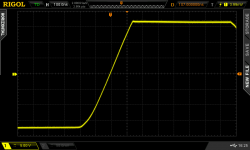
Speaking of opamps, here's one I built yesterday. All bipolar, conventional voltage feedback amplifier (single diffpair, then NPN gain stage, then complementary EF output stage) using the Sanyo / ON Semi 2SC6043 / 2SA2127 super fast, low voltage BJTs.
Faster than the heavenly NE5534A (0.87 V / us / V) which people here seem to absolutely love.
_
- 20V supply rails, 35 V slew in 320 nsec = 109V/usec = 5.4 V / us / volt of supply rail.
_
Attachments
P.S. Setting absurd engineering requirements, without any justification other than 'because I say so", and in particular when you know you don't have to do it yourself, also costs nothing, isn't it?
Look Waly, they dont have to be Your standard. They are my standard for my challenge and enjoyment and pursuit.
And, I do a LOT of things with other more talented people who pick up the challenge for thier own reasons. And, I modify test equipment to suit my agenda, too. I do not feel like I have to know how to do everything myself and do it better than anyone else.
Some other forums I have pic'ed the curiosity and talents to design lower distortion, variable freq audio generators than available commercially. And, then how to measure it. Also, far below what might be audible. As you have said -- I dont think you get it.
THx-RNMarsh
Last edited:
Speaking of opamps, here's one I built yesterday. All bipolar, conventional voltage feedback amplifier (single diffpair, then NPN gain stage, then complementary EF output stage) using the Sanyo / ON Semi 2SC6043 / 2SA2127 super fast, low voltage BJTs.
Faster than the heavenly NE5534A (0.87 V / us / V) which people here seem to absolutely love.
- 20V supply rails, 35 V slew in 320 nsec = 109V/usec = 5.4 V / us / volt of supply rail.
_
Into 600 Ohm load... how does it perform? And to My point, what is the THD as you approach that SR limit? In your case it would show up at HF. In a PA?
-RNM
Last edited:
Really, since when is 2.5V/uS per volt "fairly good"? I though this is a minimum for you, you just suggested 4-6V/uS per volt as something you are comfortable with.
I said 2v/us/v was a minimum (to attain my goal of lowest thd). But that the suggested 4-6 (or more) is fine as well.
THx-RNM
Last edited:
Look Waly, they dont have to be Your standard. They are my standard for my challenge and enjoyment and pursuit.
And, I do a LOT of things with other more talented people who pick up the challenge for thier own reasons. And, I modify test equipment to suit my agenda, too. I do not feel like I have to know how to do everything myself and do it better than anyone else.
Some other forums I have pic'ed the curiosity and talents to design lower distortion, variable freq audio generators than available commercially. And, then how to measure it. Also, far below what might be audible. As you have said -- I dont think you get it.
Uh-oh. I do get it, but I will stop short of telling what I think about. You wouldn't get it.
- Home
- Amplifiers
- Solid State
- Bob Cordell's Power amplifier book